Robot workcell design: test the layout before you build
Plan robot workcells in 3D. Compare layouts, check robot reach and motion, and test production flow before installation with Visual Components.
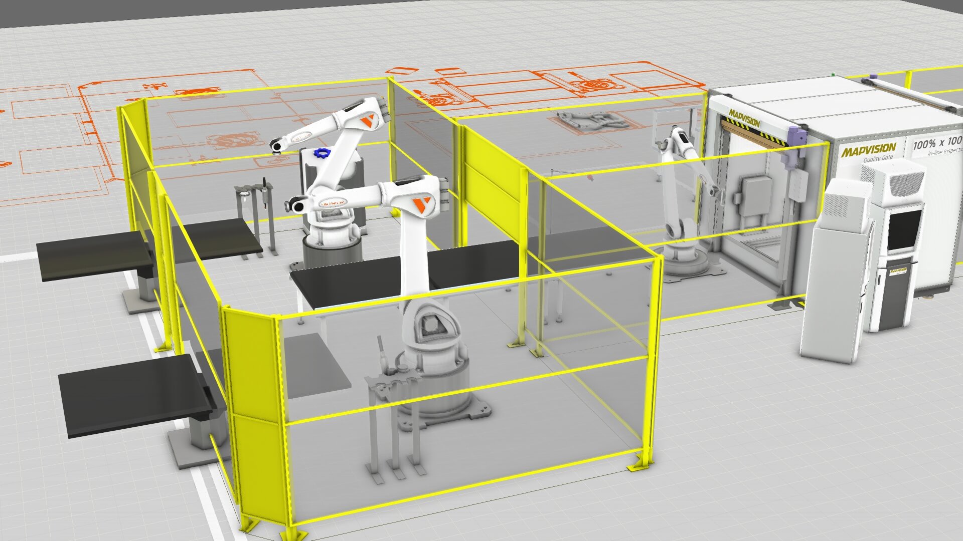
The robot reaches the part on paper. In the cell, the tool has to approach at the right angle without hitting a fixture, and the next part has to arrive when the robot is ready. With Visual Components, you can compare 3D layouts, check robot motion, and test production flow before installation.
Planning a cell? Talk to a Visual Components expert about your layout, the robot’s task, and your target output. Together, we can identify what to model and what you’ll need to check on the real cell.
What is a robot workcell?
A robot workcell, also called a robotic cell, includes the robot, its end effector, the part, a fixture or machine, and equipment to move parts in and out. People also need room to operate and maintain it. Which components you need depends on the task.
The layout needs to let the tool reach every required position at the right angle and move without interfering with equipment in the model. The cell also needs to handle the planned flow of parts. Engineers, programmers, integrators, and operations teams can review these questions together in a 3D model.
Start with the decision, then build the model
Can the proposed robot position, tool, and layout perform the job at the required pace? To find out, gather:
- Floor space and available CAD models or drawings.
- Robot, tool, payload, part, and fixture details, including part variants.
- The task sequence, expected operation times, and target output.
- Infeed, outfeed, transfer, and buffer assumptions.
- Space needed for access, maintenance, and any planned guarding or doors.
Label unknown times and dimensions as assumptions, then test what happens when they change. An early estimate shouldn’t pass for a confirmed production result.
Compare robot workcell layouts before committing
Build a 3D cell from existing CAD data and ready-made equipment models. Try another mounting position, change the robot’s orientation, or present the part differently. The tool may need a particular approach angle even when the robot can reach the part. Clamps and nearby machines can also block its path.
Moving the robot closer might improve access to one side of the part while leaving less room for a transfer route or maintenance. Compare both layouts against the same task and output target. Then show the options to the people who will install and run the cell. They can weigh the trade-off; the software doesn’t choose the best design on its own.
For decisions that extend beyond one cell, see our factory layout design guidance.
Check robot motion and production flow at the right level
With a detailed virtual cell and the right robot offline programming (OLP) setup, you can check reach, joint movement, and potential interference along planned paths. Include the tool, part, fixtures, and other moving equipment. If the model reveals a problem, change the layout or the path. OLP can also prepare a program for a supported robot and controller configuration when you’re ready for that step.
Manufacturing simulation answers a different question: what happens to parts as work moves through the cell and on to the next operation? Add operation times, transfers, waits, and buffers. Compare modeled cycle time or throughput for each layout using the same stated assumptions. In a flow model, the robot may simply appear as a timed operation. For detailed motion, check the robot paths separately. A simulation estimate isn’t a measured production cycle. Controller-connected timing checks need a suitable setup and integration.
Visual Components manufacturing simulation covers layout and flow analysis. Robot offline programming covers detailed paths and program preparation. Modeling tools, post-processing, and controller connections vary by product, edition, and supported configuration. A manufacturing simulation license does not necessarily include OLP or virtual commissioning. Our robot simulation explainer goes into the distinction between flow and motion.
Bring the virtual cell back to the real one
Leave room for guards, doors, operators, and maintenance. You can review these needs in the model, but a path that clears modeled equipment is not a safety approval. Qualified teams must assess risks, select and validate protective measures and interlocks, and check the requirements that apply to the installed cell.
After installation, compare the equipment’s actual positions and measured timings with the model. Calibrate the virtual cell where needed, then test and validate robot programs on the physical cell before production. Visual Components provides software and related services. It does not supply the physical robot, cell, or safety equipment.
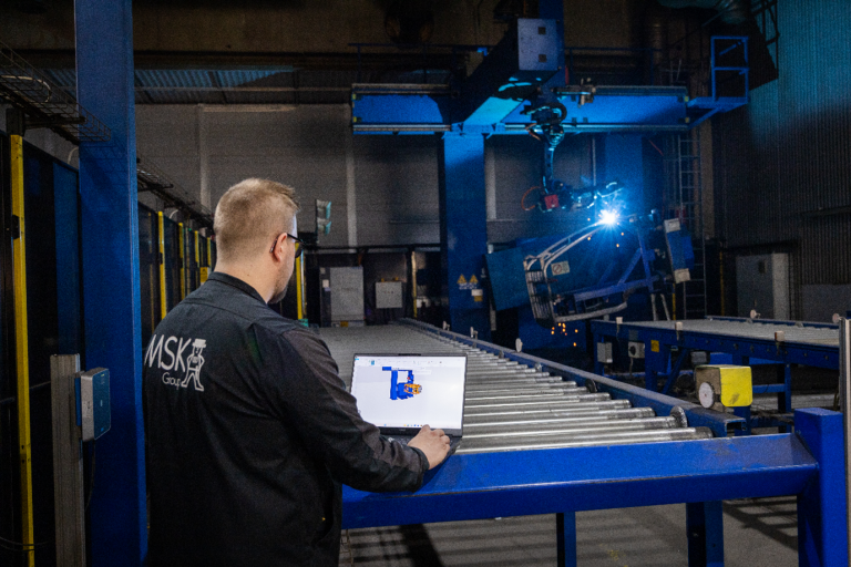
How MSK Finland planned robot cells before assembly
MSK Finland prepared several robot cells with Visual Components OLP before the equipment was assembled. Its team checked reach, reviewed jig and fixture designs, tested robot movements, and prepared programs in the virtual cell. Those checks gave MSK a head start on its own installations; the outcome will depend on the cell and how closely the model matches it.
MSK also used manufacturing simulation to study factory material transfers. That was a separate project, with no reported robot-cell throughput result.
See what your cell concept needs to prove
Bring a layout or drawing, a representative part and task, your proposed robot and tool, and a target output. We’ll look at which layout, motion, and flow questions to test in the model. We’ll also identify missing inputs and checks to make on-site.
Talk to an OLP expert and request a demo
Explore Visual Components robot offline programming.
How our customers turn possibilities into results
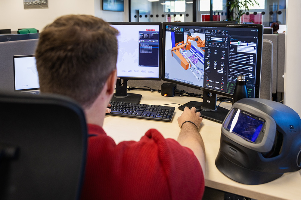
See how Bucher Municipal uses Visual Components to evaluate and optimize manufacturing concepts virtually, helping the team make informed decisions before making changes to the physical production environment.
Discover how Sandvik uses Visual Components to put manufacturing simulation into practice and support smarter production planning.
Frequently asked questions
Simulation lets you evaluate a proposed cell before committing to the physical setup. You can compare layouts, check whether the robot and tool can reach the required positions, identify potential interference, and evaluate how parts move through the cell.
The virtual model can support planning and robot program preparation, but before it can accurately represent the production cell, it needs to be calibrated using data from the real robot cell. After installation, equipment positions and robot calibration should be verified, and robot programs must be tested on the physical cell following the site’s appropriate safety procedures.
Yes. With a sufficiently detailed virtual cell, you can check robot reach, joint movement, tool orientation, and potential interference with modeled fixtures and equipment. This can help identify necessary layout or path changes before installation.
Manufacturing simulation focuses on questions such as layout, material flow, operation times, buffers, and modeled production output. Robot offline programming focuses on detailed robot motion, path creation, and preparing robot programs for supported robot and controller configurations.

Further reading
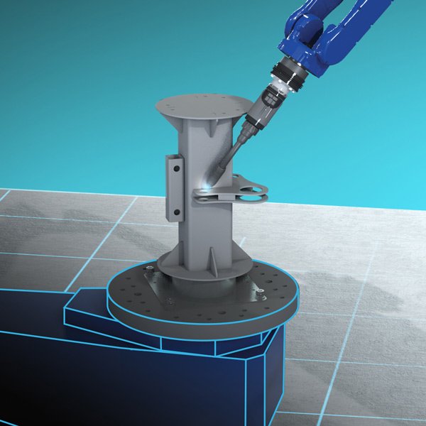
Robotic welding: plan, simulate, and program the complete cell offline
Plan robotic welding cells, check reach and collisions, and prepare robot programs offline with Visual Components OLP. See how the workflow fits your cell.
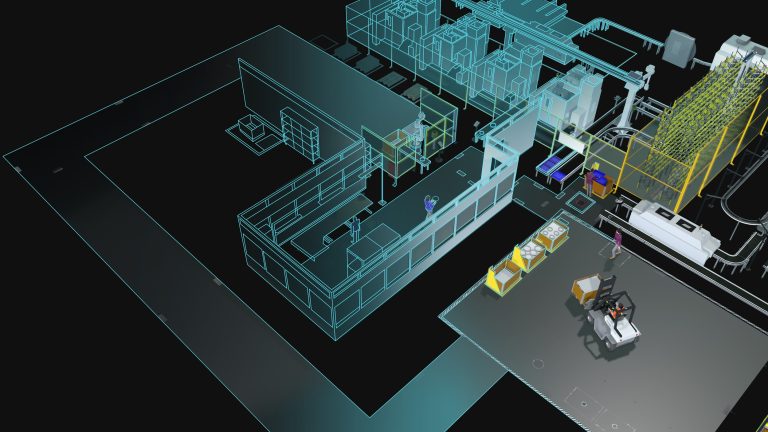
Digital manufacturing: from factory plans to better production decisions
See how digital manufacturing helps teams model new and existing production, simulate product flow, and compare options before making changes on the factory floor.

Mike Strahlman on what comes next for Visual Components
As the new CEO of Visual Components, Mike Strahlman shares his vision for the future of manufacturing simulation, digital twins, and automation planning. In this interview, he explains why factories...