Mobile robot simulation: plan and validate AMRs and AGVs before deployment
Learn how mobile robot simulation helps manufacturers size fleets, validate routes, find congestion, and plan AMR and AGV deployments before hardware arrives.
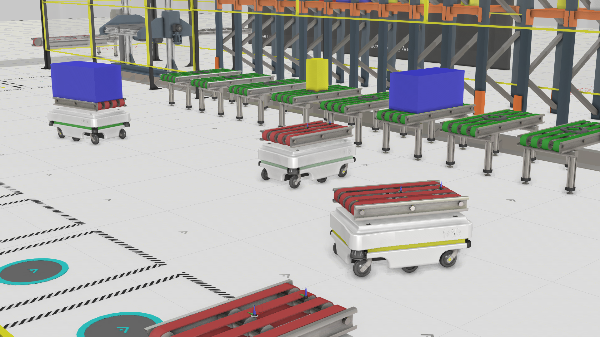
A fleet of 20 autonomous mobile robots (AMRs) and automated guided vehicles (AGVs) can look manageable on a floor plan. Then two vehicles reach the same narrow aisle. A forklift blocks the quickest alternative. A workstation runs out of parts while traffic backs up elsewhere.
A spreadsheet can estimate travel times, but it cannot show this chain reaction in enough detail. A physical pilot can, but by then the hardware has been ordered and engineers are working around real equipment.
Mobile robot simulation moves these tests to a virtual factory. Teams can compare fleet sizes, routes, charging plans, and traffic rules before they commit to a design. But the model must remain believable when the factory gets busy. A smooth animation of one AMR is not the same as a useful simulation of a working fleet.
So, what does mobile robot simulation need to get right? And how does Visual Components 5.1 help engineers test larger, more complex systems?
What mobile robot simulation needs to get right
Brand-dedicated OLP tools were built to do one thing extremely well: program and simulate robots from a single manufacturer with high fidelity.
AMRs and AGVs are often grouped under “mobile robots,” but they do not move in the same way. An AGV typically follows a predefined path or guide route. An AMR can use onboard sensors and a map to choose or adjust its route within permitted areas.
In practice, both are part of the same material flow system. They work alongside production equipment, workstations, conveyors, forklifts, and people. A useful model must account for these relationships.
Pathfinding across a shared factory floor
Finding a route for one vehicle is fairly straightforward. Add another 20 vehicles with different destinations and priorities, and the challenge changes.
Each mobile resource needs a route around walls, machines, storage areas, and other restrictions. Routes also need to update as the layout or traffic conditions change. At the same time, the model must run fast enough for engineers to compare several scenarios. If each experiment takes too long, teams cannot test enough alternatives before making a decision.
Local steering in real spaces
A route can be valid on paper and still produce poor movement in practice. Mobile resources need local steering to pass through doorways, turn in narrow aisles, move around traffic, and line up at stations.
Pathfinding answers, “How can I get there?” Local steering handles the next few meters. Good AMR simulation software needs both.
Dynamic obstacle avoidance
Factory floors do not stay still. People cross aisles. A forklift enters a traffic lane. Someone leaves a pallet near a workstation. Another mobile robot stops ahead.
Simulated resources need to respond, maintain separation, and continue when the route clears. If vehicles pass through one another, the model may report strong throughput based on behavior that cannot happen on the real factory floor.
Dense, mixed traffic
As the floor gets busier, navigation becomes a traffic management problem. A sensible choice for one robot may reduce the performance of the fleet. Vehicles can queue at an intersection, block a station, or create a deadlock where no one can move.
This is where isolated vehicle models fall short. AGV fleet simulation is more useful when it covers the wider factory. Mobile traffic affects buffers, conveyors, people, and production equipment, and each of these can affect the fleet in return.
Stable behavior over long runs
A five-minute demonstration may look convincing. It does not show whether a queue appears three hours into a shift or whether charging demand leaves too few vehicles available after lunch.
Movement needs to remain stable over longer simulation runs. Erratic steering and small navigation errors can affect routes and timing. Once that happens, the results no longer describe the operation the team intended to study.
Why earlier approaches struggled at scale
Mobile resource navigation has often relied on custom scripts. This can work for a small layout with a few fixed routes. It becomes harder to maintain as traffic rules change and more vehicles join the model.
Earlier Visual Components workflows faced the same limitation. Custom navigation could be slow and difficult to scale. Dynamic obstacle avoidance was not built in, so resources could clip through one another. Movement in larger simulations could also become unstable over time.
Teams had to choose where to compromise. Simplifying behavior made a larger model easier to run, but the model revealed less. Adding detail increased setup work and could reduce performance.
Unrealistic movement also changed the results. Vehicles that passed through each other never formed real queues, so the model could overstate throughput. Unnecessary hesitation could push the estimate in the other direction.
What changes in Visual Components 5.1
Visual Components 5.1 introduces a new navigation system for mobile resources. The update focuses on the outcomes engineers need when they model busy industrial layouts: faster pathfinding, smoother local movement, dynamic avoidance, and stable behavior in mixed traffic.
In Visual Components 5.1:
- Built-in pathfinding reduces the need to create every navigation behavior with custom scripts.
- Local steering helps resources move through corridors, intersections, and tight spaces more naturally.
- Mobile resources respond to other moving resources instead of clipping through them.
- Dense, mixed-resource simulations remain more stable over long runs.
- One model can include mobile robots, forklifts, people, conveyors, and production equipment.
These changes make it more practical to test the fleet as part of the whole production system. Engineers can spend less time building basic navigation behavior and more time comparing design choices.
There is still work for the engineer. Simulation software cannot know the correct speeds, process times, task logic, charging behavior, or traffic rules without reliable input. These assumptions determine how useful the results will be.
A planning simulation also cannot reproduce every detail of the real fleet manager, vehicle hardware, and control software unless it connects to the actual or emulated control system. Hardware- and software-specific behavior may differ from the model. Even without that connection, the simulation can provide enough accuracy to compare fleet sizes, check whether the solution concept is valid, and find likely bottlenecks. Teams should use it for those decisions rather than treat it as a perfect prediction of the deployed system.
What you can test before buying hardware
The point is not smoother animation. It is the ability to answer harder questions before buying hardware or changing the factory floor.
Find the right fleet size
Too few vehicles can starve workstations and reduce output. Too many can increase cost and create congestion that cancels out the extra capacity.
Run the same demand with different fleet configurations. Add or remove vehicles and compare throughput, waiting time, utilization, and queues. The goal is usually to find the smallest fleet that meets the required service level while leaving room for normal variation.
Validate routes and traffic rules
The shortest route for each robot does not always produce the best system flow. A slightly longer one-way loop may perform better than two-way traffic through a narrow aisle. A priority rule at one intersection may stop queues from spreading into production areas.
Test these alternatives before anyone marks lanes or moves equipment. A model can expose deadlocks, blocked stations, and pedestrian crossings that looked harmless on the floor plan.
Plan charging and task allocation
Battery charging affects fleet availability. A charging strategy that looks reasonable on paper can create a queue at the wrong time or leave too few vehicles available during peak demand.
Charging cannot be planned separately from the work. Include charger locations, task dispatch rules, and changing demand in the same model. The vehicle count may be right while the charging plan is not.
Study shared spaces
Manufacturing rarely happens on a robot-only floor. People, forklifts, AGVs, and AMRs often use nearby or overlapping routes.
Simulation helps teams review traffic separation, crossing points, visibility, and safe zones while they can still change the layout easily. It supports safety planning, but it does not replace a formal risk assessment or compliance with applicable safety standards.
Prepare for virtual commissioning
Planning simulation helps determine whether the proposed system can meet its goals. Virtual commissioning goes further. Teams connect real or emulated control logic to the virtual model, then test sequences, signals, and fault handling before startup.
For a mobile robotics project, start by validating movement and material flow. Then confirm which interfaces are available for the selected fleet manager, programmable logic controller (PLC), and mobile robot system. Visual Components 5.1 adds Allen-Bradley PLC connectivity, but this does not mean it connects to every AMR or AGV controller. The commissioning setup depends on the selected hardware, software, and interfaces.
Connecting the model to the real or emulated fleet manager can improve accuracy by including more of the system-specific dispatching and control behavior. It also changes the purpose of the test. The team is no longer only evaluating a planning assumption. It is checking how the intended control system behaves in the virtual factory.
Mobile robots are a practical step toward physical AI
Many AGVs follow fixed routes. AMRs make more navigation decisions, but usually within a mapped area and a defined set of rules. Physical artificial intelligence (AI) moves further toward machines that can perceive their surroundings and decide how to act.
Mobile robots are a practical early example of this direction. They already use sensors to respond to changing conditions. As autonomy increases, teams need to test more behaviors, including situations that would be expensive, disruptive, or unsafe to stage in a live factory.
Simulation can repeat these situations without putting people or equipment at risk. The mobile resource improvements in Visual Components 5.1 create a stronger environment for this work. They provide useful groundwork for broader physical AI workflows, but they do not turn Visual Components into a complete physical AI training platform.
A good vehicle can still make a poor fleet
A mobile robot can work well on its own and still be part of a poor fleet design. The real questions are whether stations receive material on time, where traffic builds up, and how the system recovers when an aisle is blocked.
Teams can answer these questions faster and at a lower cost before the vehicles arrive. Visual Components 5.1 makes larger and busier mobile robot simulations more practical. This helpsengineers assess the fleet as part of the production system instead of viewing it as a set of vehicles moving in isolation.
Explore manufacturing simulation with Visual Components
Further reading

Mike Strahlman on what comes next for Visual Components
As the new CEO of Visual Components, Mike Strahlman shares his vision for the future of manufacturing simulation, digital twins, and automation planning. In this interview, he explains why factories...
Cost per weld: how to compare robot programming software as production scales
Calculate robot programming software cost per weld and compare license, subscription, and weld-credit pricing as parts and variants scale.
Introducing FactoryLens: turn factory simulations into realistic customer experiences
Visual Components launches FactoryLens, extending its collaboration with NVIDIA for industrial digital twins. FactoryLens helps system integrators and machine builders present Visual Components simulations with realistic materials, lighting, and shadows,...