Robotic welding: plan, simulate, and program the complete cell offline
Plan robotic welding cells, check reach and collisions, and prepare robot programs offline with Visual Components OLP. See how the workflow fits your cell.
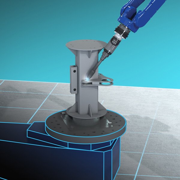
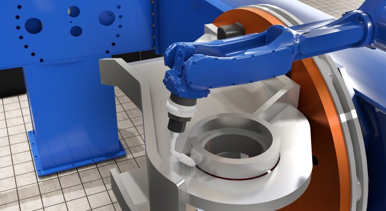
A weld may look accessible on a drawing, yet the torch hits a clamp on the way in. Visual Components helps you check robotic welding paths in a virtual cell and prepare robot programs while the production cell keeps running.
Planning a new cell or changing an existing one? Request a demo using a representative part, robot and controller, fixture, and positioner. We can show you how the workflow fits your setup.
What does robotic welding involve?
A robotic welding cell has a robot, a torch, a workpiece, and a fixture to hold it. Many cells also have a positioner that turns the part to maintain the optimal welding angle throughout the seam. The robot needs a clear path to each joint, room to move between welds, and a program its controller can run.
Visual Components provides simulation and robot offline programming (OLP) software for planning and programming the cell. You can prepare new jobs without taking a production robot out of service. We don’t sell the robot, fixture, or welding equipment. Your welding team defines the welding procedure and validates the finished welds.
Plan a robotic welding cell before you build or change it
Start with a CAD model of the part and a virtual layout of the robot, torch, fixture, and positioner. Before you build a cell or change one, check the proposed arrangement:
- Can the torch reach each joint at the angle the process requires?
- Do clamps or other modeled equipment block the torch on its way in?
- Can the robot make the move without exceeding its joint limits?
- Would moving the robot or turning the part improve access?
Compare robots, tools, and fixtures before you choose hardware
If you haven’t selected a robot yet, compare brands and models from the Visual Components eCatalog. Test different configurations against the same part and fixture to see which robots provide the reach and motion your application needs.
Use parametric tool and clamping components from the eCatalog to explore access to difficult areas of the workpiece. Adjust their dimensions to compare options. If you already use specific tools, import their actual CAD geometry and check whether they fit the task.
The modeling tools in Professional OLP and Premium OLP let you create more realistic cell models and modify geometry to match your setup. You can compare layouts while changes are still easy to make. Ponsse checks new frame designs before ordering plates, including whether the robot can access the welds.
Program and test the welding job offline
With a layout in place, set the tool center point and reference frames for the cell. Create weld paths on the part and define the optimal torch angles according to your welding procedure specification (WPS). Save those settings in templates so the software can automatically reuse them for similar welds. It also generates approach and departure motions and synchronizes the robot with the positioner to maintain the required orientation along the seam.
Run the complete sequence in simulation, including travel moves between welds. Check for collisions, joint limits, and areas the torch cannot reach. Let the automatic solver adjust paths within the maximum deviations you define according to your WPS. Review the results and revisit the tool, fixture, or layout if the solver cannot find a solution within those limits.
For arc welding on large parts, the welding speed often determines most of the cycle time. At 10 mm/s across many meters of seam, for example, the internal estimate can be close to the actual welding time. Controller-specific timing analysis adds more value in fast processes such as spot welding, where small motion differences can affect line takt time. Confirm the complete cycle time in the physical cell, including handling and other non-welding tasks.
Save programs and process settings for later jobs. For multi-pass welding, your team defines the pass logic and settings, which the software can apply to multi-layer seams. Your welding engineer remains responsible for the procedure and weld order. Export the program through a post-processor that supports your robot and controller configuration. Check controller compatibility, process options, and license scope with an OLP specialist.
Use weld data from CAD to automate path creation
Already defined your welds in CAD using model-based definition (MBD)? You can import the weld definitions and path data through QIF, XML, or IFC files in a supported workflow, rather than recreate each seam manually.
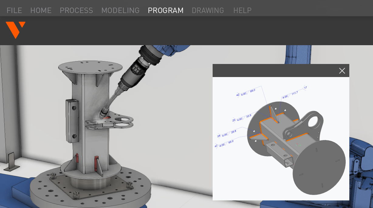
MBD connects the 3D model with product manufacturing information, such as weld locations, sizes, and joint types. With complete, machine-readable data and your welding templates in place, Visual Components OLP can use that information to create and solve robot paths automatically. Your team reviews the imported data and resulting motions before export.
See how model-based engineering connects design data with robot programming and explore the levels of OLP automation, from predefined rules to MBD. For the core programming steps, see our basic welding OLP workflow.
Bring the program into the real cell
Before you run the program on a physical cell, check the model against what was installed. Measure and calibrate the robot, torch, workpiece frames, fixture, and external axes as needed. During commissioning, test the exported program on the actual controller under your site’s safety procedures. Check motion and clearances, validate the welding process and finished welds, and make any necessary teach-pendant touch-ups.
Keep motion consistency and weld quality in view
Simulation helps you program consistent torch angles, steady travel speeds, and precise robot paths. But arc welding uses high electrical currents to melt and fuse metal. A motion simulation cannot fully predict the quality of the seam that forms.
The result also depends on welding parameters suited to the material and thickness, the shielding gas and wire combination, surface cleanliness, and joint fit-up. Rust, dust, and unexpected gaps between parts can affect the weld even when the programmed motion is correct. Validate these conditions and the finished weld in the real cell. Simulation supports that work; it doesn’t replace it.
What this looks like at Ponsse
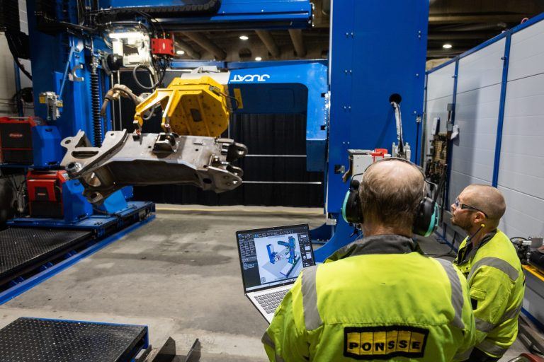
Ponsse welds complex frames for forest machines. Its team reports that programming a frame that used to take 10 days now takes one day. It checks new designs for weldability and prepares programs before a new robot station arrives. After installation, the team calibrates the cell, touches up the programs, and uploads them to the controller. The time saving is Ponsse’s reported result for its workflow, not a benchmark for every welding cell.
See how it fits your welding cell
Bring a representative part and your proposed or existing layout. Include the robot and controller, fixture, and positioner details if you have them. Still choosing hardware? We can compare options. Already using MBD? Bring a sample export so we can check how your weld data fits the programming workflow.
Talk to an OLP expert and request a demo
Explore Visual Components robot offline programming.
Frequently asked questions
Robot offline programming lets you create, simulate, and test robotic welding programs in a virtual environment instead of programming directly on the production robot. With Visual Components OLP, you can prepare new welding jobs while the physical production cell continues running.
Yes. Visual Components lets you simulate the robot, torch, workpiece, fixture, and positioner to check whether welds are reachable. You can identify potential collisions with clamps or other equipment, check robot joint limits, and test different torch angles before making changes to the physical cell.
Yes. You can compare robot models, tools, fixtures, and different cell configurations in simulation. This helps you evaluate reach, accessibility, and robot motion before committing to a particular cell layout or hardware setup.
Yes, in supported workflows. Weld definitions and path information created using model-based definition (MBD) can be imported through formats such as QIF, XML, or IFC. Visual Components OLP can then use the machine-readable weld information together with welding templates to help create and solve robot paths.
No. Simulation helps validate robot motion, torch angles, travel speeds, reachability, and potential collisions, but it cannot fully predict the quality of the physical weld. Factors such as welding parameters, materials, shielding gas, wire, surface condition, and joint fit-up still need to be validated in the real production cell.

Further reading
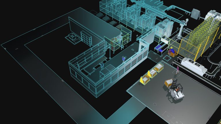
Digital manufacturing: from factory plans to better production decisions
See how digital manufacturing helps teams model new and existing production, simulate product flow, and compare options before making changes on the factory floor.

Mike Strahlman on what comes next for Visual Components
As the new CEO of Visual Components, Mike Strahlman shares his vision for the future of manufacturing simulation, digital twins, and automation planning. In this interview, he explains why factories...
Cost per weld: how to compare robot programming software as production scales
Calculate robot programming software cost per weld and compare license, subscription, and weld-credit pricing as parts and variants scale.