Digital manufacturing: from factory plans to better production decisions
See how digital manufacturing helps teams model new and existing production, simulate product flow, and compare options before making changes on the factory floor.
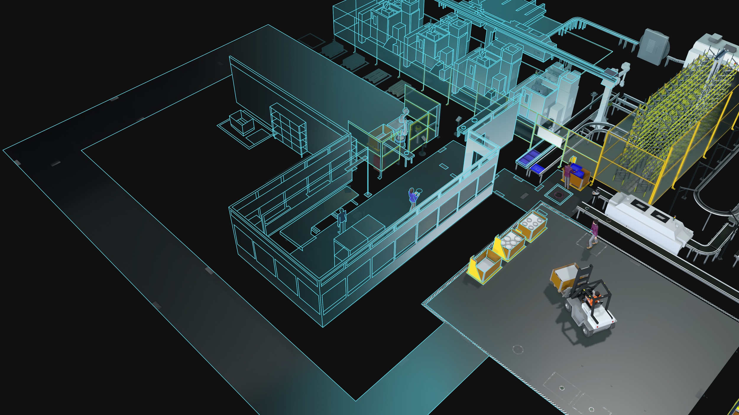
Where will products wait if one station runs slower than the next? Whether you’re improving an existing line or planning a new one, it’s a question worth answering before you buy equipment or make changes to real production. Digital manufacturing helps you test those decisions in a digital environment. With Visual Components, you can build a 3D production layout, simulate how products flow through it, and compare options with the people who will run the line.
What is digital manufacturing?
Digital manufacturing is an integrated approach that uses computer systems, 3D modeling, data analysis, and simulation to design, test, and improve production processes. It connects digital information and tools across planning and operations, helping teams evaluate decisions before putting them into practice. Real-time production data can support this work where suitable connections are available, but you don’t need a live factory connection to start planning with simulation.
For example, you can position equipment in a digital environment based on existing drawings and plant blueprints. Then you can simulate whether the proposed assembly line can handle the expected product mix and volume.

CAD shows where equipment fits. Manufacturing simulation lets you model what happens over time: when a station finishes a task, where the product goes next, and whether products queue up at the next station. A layout can fit on the floor and still create delays in production.
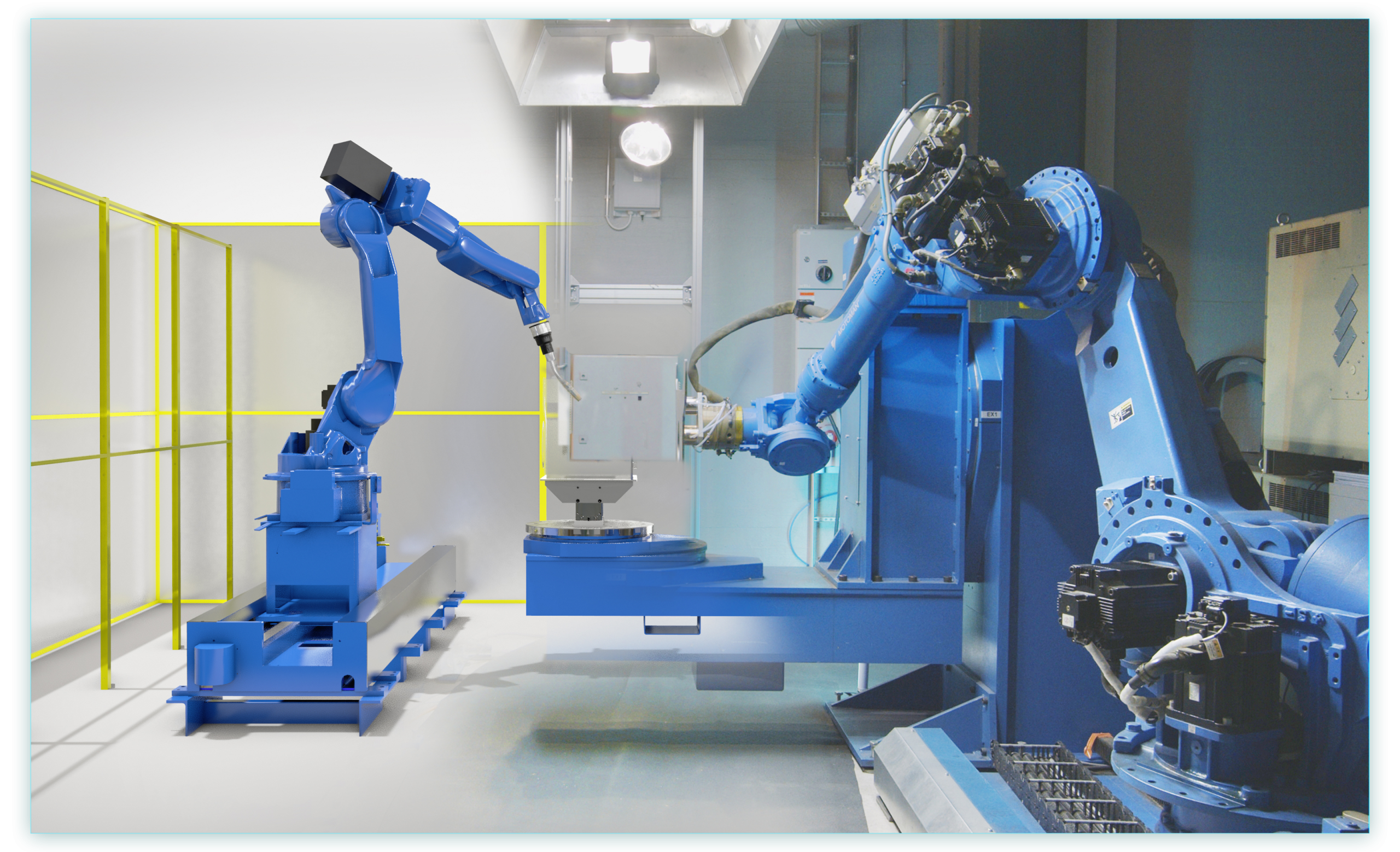
A digital twin is a more specific application that connects a digital model to a physical system. It needs suitable data and connections as well as the model itself. Not every simulation model is a digital twin, and no single software product provides every part of digital manufacturing.
Are you improving existing production or planning something new?
Simulation can support both. The difference is where your model starts and how you check its results.
Existing production: brownfield projects
In a brownfield project, you model a production system that already exists. You might want to add a machine, change a material route, or find out why products build up between stations.
Start by representing the current layout and process in the digital environment. Use existing drawings, equipment dimensions, and observed operation times. Compare the model’s behavior with actual production before testing proposed changes. This gives your team a checked starting point for evaluating alternatives.
New production: greenfield projects
In a greenfield project, you model a new production system before it’s built. You can compare equipment layouts, material routes, and capacity options before installation.
Build the model from plant blueprints, proposed equipment, supplier information, and the planned product mix and volume. Some inputs will be estimates. Make those assumptions clear and test how changes to them affect the results. Update the model as equipment details become available, then check it against actual production once the line is running.
Start with the production decision
Choose the question your team needs to answer. You may only need to model one cell or line:
- Where should new equipment go within the available floor space?
- Can the existing line handle a different product mix or higher volume?
- Can a proposed line reach its target output under the planned operating assumptions?
- Where could products queue up, and would another machine or a different route help?
Gather the inputs that matter to that choice: floor plans or CAD data, equipment dimensions, process sequence, operation times, and expected production volumes. Include space for people and material movement. Keep measured data separate from estimates so everyone understands what the simulation results are based on.
How digital manufacturing turns a plan into a testable model
Build the digital layout
Bring existing drawings or CAD data into the digital environment, or assemble a 3D layout from ready-made equipment models. For a brownfield project, represent the equipment and space already in use. For a greenfield project, position the proposed equipment within the planned building or production area.
Visual Components supports 3D layouts built from its component library and imported data. Import and modeling options vary by product and workflow. Place the stations and check how much space they need. Our factory layout design guide covers this step in more detail.
Model how products flow
Set out what each station does, how long it takes, and where products go next. Include handoffs and buffers where products could wait. Now you can simulate the production process instead of reviewing equipment positions alone.
For existing production, check that the model reflects the flow you observe on the floor. For a new line, review process logic and timing assumptions with your team and equipment suppliers.
Compare options against the same question
Try a different layout, change the number of machines, or adjust a buffer to see how it affects waiting time. In a brownfield project, compare proposed changes with the current-production model. In a greenfield project, compare alternative designs against the same production targets.
Keep the product mix and operating assumptions consistent unless you’re testing their effect. One configuration may free up space but lengthen a material route. Another may relieve a modeled bottleneck but need more equipment. Those trade-offs help your team assess the options before committing to a purchase or physical change.
You can start with a cell or line and expand the model when the decision calls for it. Larger plant models need more input detail and computing resources.
Make the decision together
A shared 3D model gives everyone a view of the production system and the changes under discussion. Engineers can check equipment placement and process logic. Operations staff can challenge timing assumptions or flag a material route that would block access. A system integrator can show how a proposed system is intended to work. The team can then revise the scenario together before installation or changes to real production.
Some projects also use virtual commissioning to test control logic against a digital model before physical commissioning. That takes additional modeling and suitable control-system connections. Building a layout alone doesn’t do it; available integrations depend on the product configuration.
What did AGCO Power learn before expanding its factory?
An expansion can combine an existing factory with a new production system. Before ordering equipment for an expansion of its diesel-engine factory in Nokia, Finland, AGCO Power had its proposed component-machining system simulated.
Jetecon built a 3D model based on AGCO Power’s production plans. The simulation found bottlenecks caused by too little equipment in parts of the plan. It also showed where fewer machines might be enough. AGCO Power used the model to compare equipment from different suppliers, according to the published AGCO Power case study.
The model helped the team examine equipment needs before ordering. The case reports a planning experience, not a measured throughput gain or a quantified investment saving.
Take the model back to the factory floor
Review the model’s inputs with the people who know the process. For existing production, compare simulated results with observed output and update the model when they differ. For new production, revisit estimates as you get firm equipment details, then validate the model with operating data after startup.
Simulation supports the decision; it doesn’t replace installation planning, safety assessments, or physical commissioning. Account for those requirements and daily operating constraints as you move from the digital model to real production. Keep checking results against the plan as conditions change.
Planning a new line or improving an existing one? Contact Visual Components to discuss a specific layout or production-planning question. You can also explore our manufacturing simulation software to see how it supports layout and scenario planning.
Frequently asked questions
Digital manufacturing uses technologies such as 3D modeling, simulation, and data analysis to design, test, and improve production processes digitally. With Visual Components, manufacturers can build 3D production layouts, simulate processes and product flow, and evaluate different production scenarios before making changes on the factory floor.
Visual Components can help teams investigate questions such as:
- Where should new equipment be placed?
- Can the line handle a higher volume or different product mix?
- Can a proposed line achieve its target output?
- Where are products likely to queue or wait?
- Would adding a machine, changing a buffer, or using a different material route improve the process?
By comparing alternatives in a shared 3D environment, engineering, operations, and system integration teams can evaluate trade-offs before making physical changes.
Manufacturing simulation shows how production behaves over time, including how long each process takes, where products move next, and where queues or waiting times may occur. By testing different layouts, machine quantities, buffers, and material routes in Visual Components, manufacturers can identify potential bottlenecks and compare solutions before investing in equipment or modifying production.
Yes. For brownfield projects, simulation can model an existing production system to evaluate changes such as adding equipment, changing material routes, or increasing production volume. For greenfield projects, it can help compare layouts, equipment configurations, capacity, and material flows before the new production line is installed.
Manufacturing simulation allows you to model and test how a production system could operate under different conditions. A digital twin goes further by connecting a digital model to a physical system using suitable data and system connections. Not every manufacturing simulation is therefore a digital twin, and simulation can provide valuable planning insights without requiring a live connection to the factory.
Further reading

Mike Strahlman on what comes next for Visual Components
As the new CEO of Visual Components, Mike Strahlman shares his vision for the future of manufacturing simulation, digital twins, and automation planning. In this interview, he explains why factories...
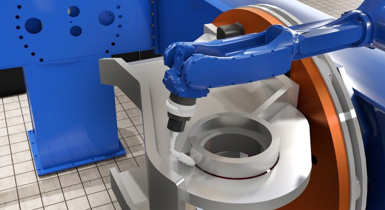
Cost per weld: how to compare robot programming software as production scales
Calculate robot programming software cost per weld and compare license, subscription, and weld-credit pricing as parts and variants scale.
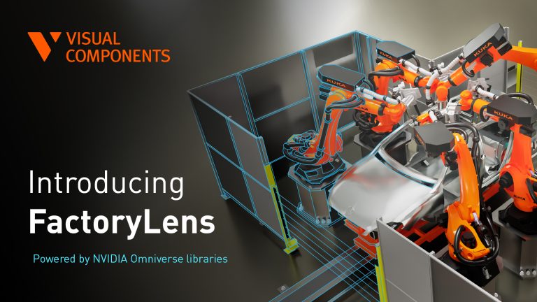
Introducing FactoryLens: turn factory simulations into realistic customer experiences
Visual Components launches FactoryLens, extending its collaboration with NVIDIA for industrial digital twins. FactoryLens helps system integrators and machine builders present Visual Components simulations with realistic materials, lighting, and shadows,...