How to program a FANUC robot offline with Visual Components
Learn how to build, calibrate, validate, post-process, and deploy a FANUC robot program offline with Visual Components.
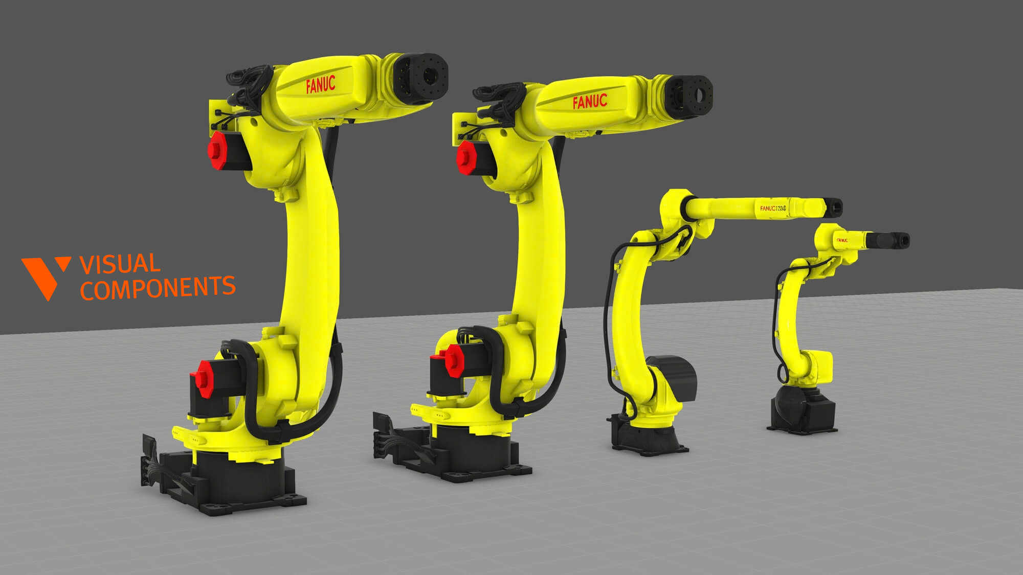
Programming a new job at the teach pendant takes the robot away from production. It can also leave reach, collision, and process problems until commissioning, when they take longer to fix. FANUC offline programming moves much of this work into a virtual cell. You can prepare the next job while the real robot keeps working.
Offline programming (OLP) lets you create and test a robot program in a 3D environment. Once the program is ready, you post-process it for the target FANUC controller, convert it to the required format, transfer it through an approved method, and verify it on the real system.
OLP reduces your dependence on the physical cell. It doesn’t replace calibration, controller backups, process validation, machinery safety procedures, or final checks on the robot.
In short: To program a FANUC robot offline, build and calibrate an accurate virtual cell using the user tool and user frame data from the real robot. Create paths from the process geometry and validate the complete sequence. Then post-process the program for the FANUC controller, convert the ASCII .LS file to binary .TP format when required, transfer it, and verify it at reduced speed under your site’s safety procedure.
What do you need before programming a FANUC robot offline?
Start with current data from the real cell. A robot model and a computer-aided design (CAD) file aren’t enough. You will need:
- The exact FANUC robot model and axis configuration
- The controller family, software version, and installed application options
- A current robot backup and the site’s approved program-transfer method
- Access to the appropriate FANUC ASCII conversion or compiler tool when .LS programs must be converted into binary .TP files
- Cell geometry, including tools, fixtures, guards, positioners, tracks, machines, and workpieces
- User tool data, including the tool center point (TCP), and the relevant user or workpiece frames
- Payload, joint limits, home positions, and other robot settings used by the real system
- Process requirements, such as speeds, tool angles, approach and retract rules, process parameter changes, I/O, and external-axis behavior
- A commissioning plan that covers backups, change control, reduced-speed verification, and rollback
“FANUC-compatible” isn’t specific enough. The robot, controller, installed software, process package, and cell architecture all affect the required program. Confirm the exact combination with your OLP supplier, integrator, and FANUC representative before you build a production workflow around it.
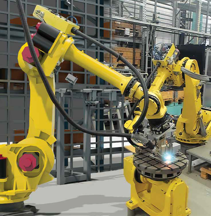
If you’re new to OLP, read our complete guide to offline programming for a broader introduction.
Which FANUC OLP software workflow fits your cell?
There are several ways to program a FANUC robot. The right option depends on the job and how closely you need to reproduce controller behavior before commissioning.
Teach pendant and on-robot programming
The teach pendant remains useful for final verification, recovery, small changes, and simple jobs. You have direct control of the real system. The trade-off is that you need access to production equipment. Teaching every point can also take a long time when a program has many seams, product variants, or coordinated axes.
FANUC ROBOGUIDE
FANUC describes ROBOGUIDE V10 as PC software for creating programs and simulating robotic workcells in 3D. Its 64-bit architecture supports larger, more detailed workcells and a wider range of CAD models than earlier versions. It also offers drag-and-drop robot setup and can display virtual pendants for several controllers at the same time.
ROBOGUIDE includes tools for specific applications. These include HandlingPRO, PaintPRO, PalletPRO and PalletTool, WeldPRO, and iRPickPRO. This FANUC-native environment is a practical choice when you need a virtual pendant, a FANUC application package, or close access to controller behavior.
Visual Components Robotics OLP
Visual Components Robotics OLP provides a graphical, brand-neutral environment for programming robots as part of a complete cell. Its supported post-processor brands include FANUC. You can model one robot or several robots together with external axes and the equipment around them.
Visual Components takes a feature-based approach to path creation. You define the operation on the workpiece instead of teaching every point through a physical or virtual pendant. You can then jog the robot and edit individual positions when a generated path needs an exception.
The two environments can also work together. Visual Components can handle feature-based program creation and full-cell simulation. FANUC software or controller connectivity can then add controller-specific validation when the project requires it.
The seven-step FANUC offline programming workflow
Step 1: build and calibrate an accurate virtual FANUC cell
Choose the exact FANUC robot model. Check its reach, payload, mounting orientation, and axes. Then add everything that can affect motion or the process. This normally includes the robot base, tool, workpiece, fixtures, positioner or track, machine, guards, and nearby equipment.
The Visual Components eCatalog offers thousands of ready-made components, including FANUC robots. You can also import customer CAD.
Visual similarity isn’t enough. Dimensions, mounting positions, kinematics, and axis relationships must match the real cell. Calibrate the virtual model with measurements and the user tool and user frame data from the real robot. If a fixture is misplaced or the positioner geometry is wrong, a path that runs in the simulation can fail during commissioning.
Step 2: calibrate the TCP, frames, payload, and process data
Calibrate the TCP position and orientation at the real functional point of the tool. Then match it with the user tool data on the FANUC teach pendant. For an arc welding torch, the TCP is the working wire-tip position. It isn’t the robot flange or an approximate point on the CAD model.
Define the relevant user or workpiece frames and their relationship to the robot and positioner. Match them with the real FANUC system. Add the payload and the process data required by the approved workflow.
A well-made path will still miss its target if the TCP, user frame, fixture location, or cell calibration is wrong. Complete this work before refining the program. Visual Components Professional OLP includes extended calibration tools for teams that commission their own robot cells.
Step 3: create paths from the workpiece and process
Build the path around the process. For a welding job, select the seam geometry, set the torch angle and travel speed, and add approach and retract motions. A handling or machine-tending job needs pick-and-place positions, enough clearance, and the relevant process events.
Because the operation stays tied to the workpiece, you don’t have to rebuild the path point by point when the product changes. You can also reuse much of it with another robot. Check reach, configuration, process commands, and post-processed output for the new system.
Graphical programming still requires engineering judgment. Jog and edit points when a path needs adjustment. The automated path solver can address reach, robot configuration, and collision issues according to limits set by the user. These limits can include required welding angles, deburring offsets, and other process constraints. An engineer still needs to review the result and approve the process.
For a closer look at this approach, see how automated robot offline programming works in Visual Components.
Step 4: configure positioners and coordinated motion
If the cell has a positioner or rail, model its location, kinematics, limits, and relationship to the workpiece. In welding, a positioner can keep the seam at a workable angle while the robot follows it. Visual Components can synchronize the robot and positioner in the virtual workflow. You can then adjust the motion when needed.
Coordinated-motion systems vary between projects. Their generated syntax depends on the motion groups, process options, and controller configuration. Before deployment, confirm support for the exact FANUC controller, external axes, application options, and post-processor.
Step 5: let the solver check the job, then review the result
A smooth animation doesn’t prove that the program is ready. Use the automated path solver to check the motion and highlight issues. Then review its results together with the complete process.
The solver can check:
- Reachability at process and transition points
- Joint limits, wrist flips, configuration changes, and singularities
- Collisions involving the robot, tool, fixtures, workpiece, positioner, guards, and other modeled equipment
- Approach, retract, and other air motions
- External-axis synchronization and clearances
The engineer must also review:
- Tool orientation and process constraints
- Process parameter changes during the operation
- Cable behavior and any other conditions not represented fully in the model
- I/O and sequence logic where these have been modeled
- Cycle time at the appropriate validation level
- The complete process result, not only robot motion
Visual Components uses an internal motion model for planning-level cycle-time estimates. These estimates help you compare layouts and find bottlenecks, but they don’t reproduce controller-level timing. When a project needs closer validation of FANUC paths and cycle times, Visual Components Premium OLP can connect to supported FANUC physical controllers or robot software. The approved endpoint and setup depend on the project.
Simulation supports engineering and reduces risk. It doesn’t certify machinery safety or replace a formal risk assessment.
Step 6: post-process for the FANUC controller
Once the program passes the simulation checks, a post-processor converts the validated robot statements into the syntax and structure required by the selected FANUC workflow. Choose the approved FANUC post-processor and enter the required project parameters.
Read through the generated program before transfer. Check program names, frames, positions, speeds, process calls, I/O references, external-axis data, and dependencies.
Visual Components post-processors use Python. Users can modify the post-processor files when a system uses customized syntax, naming rules, or functions. Treat every modification as production code. Document it, test it against a known configuration, and control its revisions. It will also need maintenance when controller software or site standards change.
The post-processor can produce a human-readable ASCII .LS program for the supported FANUC configuration. If the target controller requires binary .TP format, convert the .LS file with the appropriate FANUC ASCII conversion or compiler tool before transfer. Use the tool and version approved for the target controller.
Step 7: transfer, verify, and commission safely
Back up the target controller and follow the site’s change-control process before transferring anything. Use the approved transfer method for that cell. FANUC installations don’t all use the same route.
If your workflow starts with an ASCII .LS file, convert it to the required binary .TP format before loading it on the robot. At the target system, confirm the user tool and user frame data, payload, I/O, position registers, application settings, and program dependencies.
Follow the integrator’s or end user’s safety process. Verify the motion at reduced speed. Check calibration, clearances, interlocks, and the actual process result. Make any required touch-ups and measure the real cycle time before you approve the program for production.
Record every change made at the robot in the offline project. This keeps the offline master aligned with production.
Visual Components, ROBOGUIDE, or a combined workflow?
| Requirement | Practical workflow |
| Fast graphical path creation from CAD | Visual Components Robotics OLP |
| Full-cell or mixed-brand simulation | Visual Components Robotics OLP |
| FANUC-only virtual-pendant workflow | FANUC ROBOGUIDE |
| A specific FANUC package such as WeldPRO or PaintPRO | Confirm and validate in the FANUC environment |
| Planning-level cycle estimate | Visual Components internal motion model, clearly labeled as an estimate |
| Controller-level path and cycle-time validation | Visual Components Premium OLP FANUC connectivity and/or ROBOGUIDE, based on the approved setup |
| Reuse of workpiece-based paths across robot brands | Visual Components feature-based workflow, followed by system-specific review and post-processing |
Choose based on the application, controller requirements, fleet mix, team skills, and timing accuracy you need. A FANUC-only team may prefer ROBOGUIDE. An integrator working with several brands may prefer one feature-based environment. Some projects use both.
Practical example: a FANUC ARC Mate welding cell
Our guide to robot offline programming for welding uses a FANUC ARC Mate 120iD. The virtual cell includes a welding torch, fixture, workpiece, and positioner.
The programmer sets the torch TCP and workpiece reference. They also configure the relationship between the robot and positioner. Checks on tall seams, reach, joint behavior, torch angles, and collision pairs come before the complete weld program.
Next, they define weld paths from the part geometry. They add approach and retract motions and set the process parameters. The simulation covers the complete sequence, including robot-positioner motion and the transitions between welds. The final steps are post-processing for the approved FANUC configuration and controlled verification on the real system.
This example demonstrates program creation from CAD. It doesn’t include cell calibration steps and relies on accurate CAD models and configured data. A production project must calibrate the virtual cell against the real system before deployment.
You can adapt the overall method to handling, painting, palletizing, and machine tending. Each application still needs its own process data, controller options, and validation steps.
Take FANUC robot programming off the shop floor
Reliable FANUC robot programming starts with a virtual model that matches the real cell. Build and calibrate the model with real user tool and user frame data. Create paths from the process geometry, let the solver check the motion, and review the complete job. Then post-process for the target controller, convert the program to the required file format, and verify it on the real robot.
OLP helps you solve problems before you need the production cell. Calibration and controlled commissioning remain essential.
Frequently asked questions
Yes, for supported configurations. Model the positioner and its relationship to the workpiece. Then validate coordinated motion, limits, clearances, and generated output. Confirm the exact FANUC motion groups, controller options, and post-processor support for the project.
Check the controller backup, user tool data, TCP, user frames, payload, I/O, position registers, application settings, dependencies, calibration, and interlocks. Follow the site’s safety process, run controlled reduced-speed verification, inspect all clearances, and validate the actual process result before approving production.
Yes. You can create and simulate a FANUC robot program on a PC, post-process it for a supported controller configuration, convert it to the required file format, and transfer it to the robot. You must still calibrate the cell and verify the program on the real system before production.
You can reuse workpiece geometry, feature-based paths, and much of the process intent. After changing the robot, review reach, configurations, speeds, process commands, and external axes. Then post-process and validate the program for the new controller.
ROBOGUIDE focuses on FANUC robots, virtual-pendant use, controller behavior, and FANUC application packages. Visual Components provides feature-based path creation and full-cell simulation in a workflow that covers multiple robot brands. A project can use both for cell-level engineering and FANUC-specific validation.
Options include FANUC ROBOGUIDE and third-party OLP platforms such as Visual Components. ROBOGUIDE offers a FANUC-native environment. Visual Components supports graphical, feature-based programming and complete-cell simulation across several robot brands. Choose based on your application and required validation level.
Post-process the validated project for the approved controller configuration and review the output. If the workflow produces an ASCII .LS file, use the appropriate FANUC conversion or compiler tool to create the binary .TP file required by the controller. Back up the controller, transfer the program through the approved method, and verify it at reduced speed.
Accuracy depends on the model and validation method. An internal simulator provides useful planning estimates. FANUC controller or robot-software connectivity can provide closer controller-level path and cycle-time validation for supported setups. You still need to confirm the process and cycle on the real system.
They may. The amount depends on the accuracy of the cell model, TCP and frame data, calibration, tooling, workpiece variation, and process. Careful setup can reduce touch-up. Every program still needs controlled verification on the robot before production.
Visual Components Premium OLP can connect to supported FANUC physical controllers or robot software for path and cycle-time validation. The endpoint, controller version, software requirements, and supported functions depend on the configuration. Confirm the setup before selecting the workflow.
Yes. Visual Components supports FANUC robots and post-processors for controller generations that include R-J3, R-30iA, and R-30iB Plus. Support depends on the robot, controller generation, software options, process commands, and post-processor used in the project. Confirm the exact configuration with a Visual Components OLP specialist.
You can create standard paths and statements graphically in Visual Components without writing robot-language code. You still need to understand the robot, process, and commissioning workflow. Custom commands, post-processor changes, or unusual controller configurations may need more technical setup.

Further reading

Mike Strahlman on what comes next for Visual Components
As the new CEO of Visual Components, Mike Strahlman shares his vision for the future of manufacturing simulation, digital twins, and automation planning. In this interview, he explains why factories...
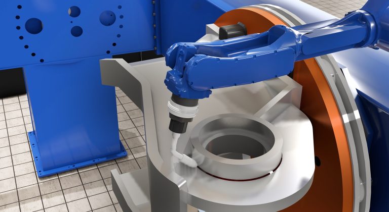
Cost per weld: how to compare robot programming software as production scales
Calculate robot programming software cost per weld and compare license, subscription, and weld-credit pricing as parts and variants scale.
Introducing FactoryLens: turn factory simulations into realistic customer experiences
Visual Components launches FactoryLens, extending its collaboration with NVIDIA for industrial digital twins. FactoryLens helps system integrators and machine builders present Visual Components simulations with realistic materials, lighting, and shadows,...