Painting robot simulation: how OLP ensures technical feasibility before production
Robot painting demands precise control of gun orientation, distance, speed, and overlap to achieve uniform film thickness on complex 3D surfaces. It cannot rely on point‑to‑point programming or CAD‑embedded path data, making offline programming (OLP) essential. This article shows how painting‑specific OLP reduces trial and error, cuts material waste, and ensures robot feasibility, turning simulation from a convenience into a critical tool for reliable paint robot deployment.
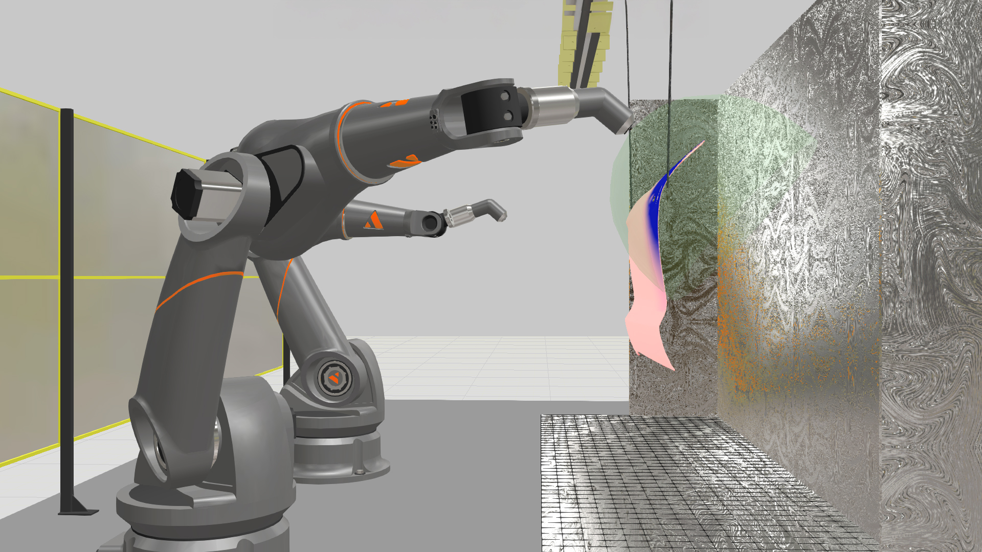
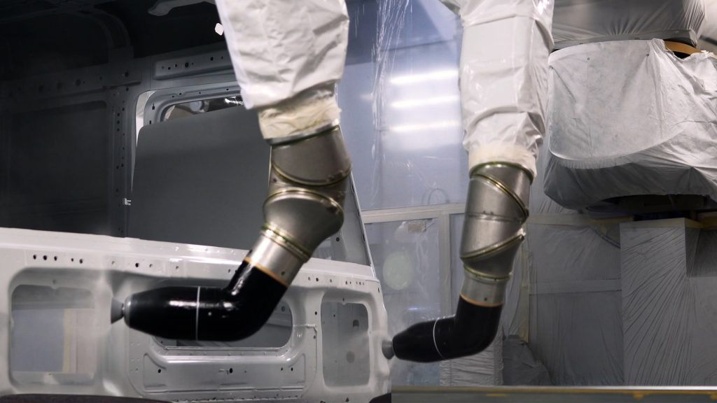
A painting robot has to hold a consistent film thickness across a complex 3D surface. The spray gun stays perpendicular to the surface, at the right distance, moving at the right speed. All at the same time. Get one of those wrong and you’re stripping the part and starting over.
Point-to-point path planning handles welding and cutting fine. Painting is different. You’re dealing with spray cone geometry, overlap between passes, surface normals that shift constantly on curved parts, and whatever the booth geometry allows. That’s why painting needs offline programming (OLP) software built for surface-based processes.
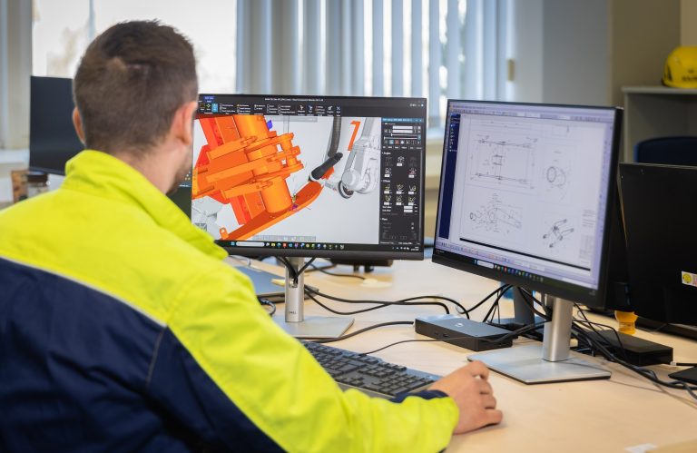
This article covers the painting OLP workflow in Visual Components OLP from CAD import to coverage validation: how spray parameters work, what Visual Components OLP simulates and where it falls short, and what the learning curve looks like. I’m Severi Keisala, application engineering manager at Visual Components. My team and I train customers and deploy these systems for a living, so everything here comes from hands-on project experience.
Painting paths don’t come from CAD
Unlike welding, where seam definitions can live inside the CAD file through PMI or MBD standards, painting has no equivalent. There’s no way to tag a surface in your native model and have Visual Components OLP pull spray paths from it. The CAD standards for painting data simply don’t exist yet.
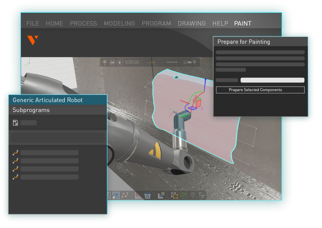
So all path creation happens inside the OLP environment after you import the model. The workflow:
- Import the CAD model (Visual Components supports all major CAD formats).
- Select the surfaces you want to coat.
- Pick a spray pattern: zigzag, spiral, contour-following, or freeform.
- Visual Components OLP generates paths perpendicular to the surface normal (90°) across the whole part.
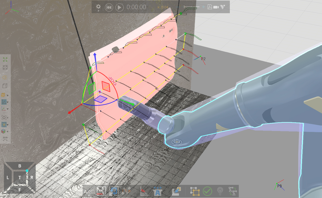
Compare that to manual teaching on a real robot, where every point has to be set one at a time while you eyeball the gun angle. Visual Components OLP calculates perpendicularity exactly. Every time.
There’s a nuance, though. Visual Components OLP forces 90° orientation relative to the surface even if that pushes the robot past its joint limits. If the robot physically can’t hold perpendicularity at some point on the geometry, the engineer adjusts the configuration or relaxes the angle constraint slightly. You can trim the tolerance to stay within what the process actually requires. It’s a deliberate choice, not guesswork.
Getting the spray simulation to match your real gun
Visual Components OLP uses a direct spray simulation model. Not computational fluid dynamics (CFD). The software doesn’t track how individual paint particles behave inside the spray cone. It estimates material deposition based on the spray profile shape, flow rate, distance from the surface, and travel speed. That estimate gets mapped onto the part surface to calculate film thickness at every point.
You configure the spray gun profile (fan width and shape), flow rate, distance, robot speed, and pattern spacing. Those are the inputs to the deposition calculation.
Calibration
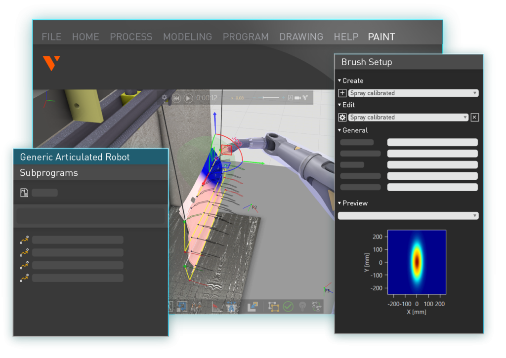
You calibrate the gun by running a physical test spray onto a flat surface and measuring the material distribution horizontally and vertically. That measurement becomes a “simulation spray gun,” a digital profile that mirrors how your real gun deposits material at a given distance.
For conventional wet-paint guns, the results are accurate. The simulation and the shop floor line up well.
Electrostatic powder coating is a different situation. Charged paint particles wrap around to the back of the part due to electrostatic attraction. A direct spray model can’t capture that. Visual Components OLP treats the spray cone as a straight-line projection from gun to surface. If something blocks the path, the paint is blocked. But particles curving around edges because of charge? That would need CFD-level physics, something like ANSYS.
We don’t pretend otherwise. For standard wet painting, the simulation is accurate. For electrostatic wrap-around, it isn’t.
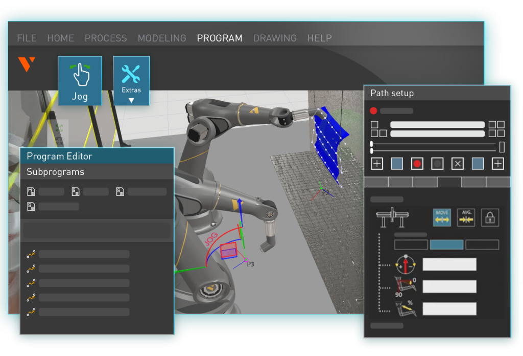
Checking coverage before the robot enters the booth
Once you have paths and parameters, Visual Components OLP gives you a few ways to see what the coating will look like:
Coverage maps confirm every target surface gets paint. A color-coded film thickness view shows how thick the coating is across the part. You can click any point and get the exact thickness value. You can also pick two points and see a cross-sectional thickness profile between them, basically a curve showing how the coating distributes along that line.
If you spot thin areas, you adjust path spacing, flow rate, or speed. If there’s too much material somewhere, you change the density or gun distance. You iterate in simulation instead of on the shop floor.
Before OLP tools existed, this was all trial and error. Program a path, spray the part, look at it, decide it’s not right, strip the coat, adjust, and spray again. With expensive processes like thermal spray, every failed test burns real money. Even with standard wet paint, repeated rounds add up.
Visual Components OLP doesn’t eliminate physical testing entirely. You’ll still confirm on the line. But you’re deploying a program that’s already been checked for coverage, thickness, and robot feasibility. Fewer surprises, fewer rounds of stripping and re-spraying.
Painting-specific constraints
| Masking |
|---|
| You define exclusion zones in Visual Components OLP so no paths get generated on surfaces that shouldn’t be coated. One thing to know: if a path runs close to an exclusion zone, the software doesn’t shape the spray cone to keep overspray out of the masked area. You still need physical masking (tape, covers, fixtures) on the floor. Visual Components OLP plans the paths. Masking is a production concern. |
| Multiple coats |
|---|
| Most painting jobs involve layers: primer, base, clear. You can reuse the same paths for each layer and just change the parameters (flow rate, speed, gun settings). If the guns are similar across layers, duplicating and adjusting is straightforward. If a different layer uses a gun with a much narrower fan, you may need to regenerate paths with tighter spacing. Same workflow, different inputs. |
| Robot kinematics |
|---|
| Painting robots are built differently from standard industrial robots. More degrees of freedom, larger joint ranges, different arm geometry. Visual Components OLP has a library with painting robot models and their kinematics preconfigured. Collision is rarely the problem. Painting robots work at a comfortable distance from the part. Singularities are the real issue: positions where the arm is fully extended and the controller can’t find a valid joint solution. In most cases, a small change in approach angle fixes it. |
When OLP goes from useful to necessary
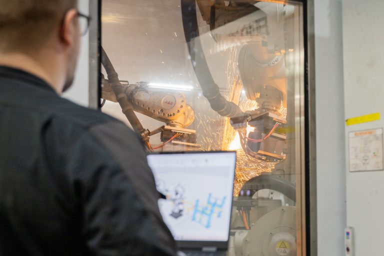
One of the harder projects I’ve worked on involved thermal spray coating with a 2,000°C plasma stream depositing material on a part surface.
The setup was inverted. The robot held the workpiece and moved it past a stationary plasma gun. Thermal spray demands near-perfect perpendicularity. If the angle is even slightly off, metal particles bounce instead of sticking.
On curved surfaces with tight radii, the perpendicularity requirement changes fast. Visual Components OLP calculated an adhesion coefficient that falls off sharply past about ±15° from perpendicular, based on published material science data.
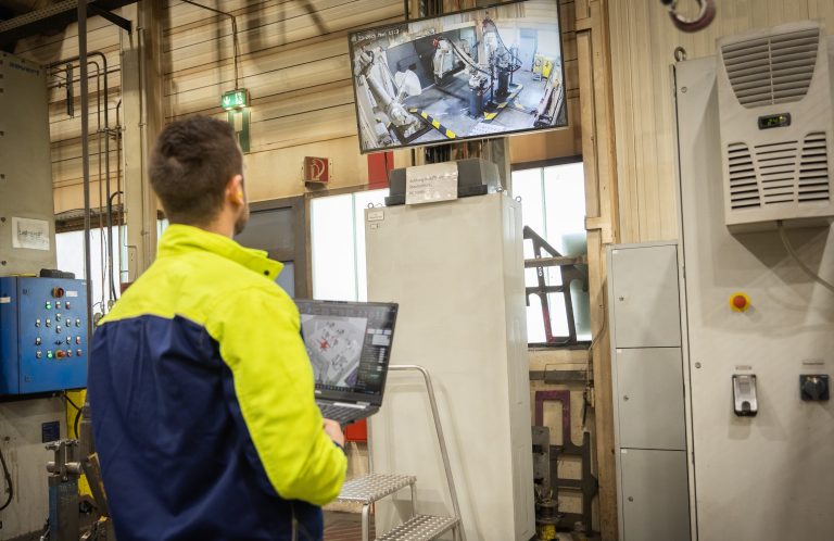
You can’t watch this process while it’s running. At 2,000°C, nobody is standing next to it checking the coating. Simulation was the only way to know the program would work before the part got coated.
For processes like that, where you physically can’t inspect during operation, OLP stops being a nice-to-have.
Learning curve
Standard onboarding for Visual Components OLP is three days. After that, engineers use the software on their own.
Some people are fast. Younger engineers who are comfortable with computers pick it up quickly. Others need more time. My team has onboarded everyone from engineers who were generating spray paths by day two, to a student who needed the first hour of training to learn how to copy and paste files. Three days later, that same person was programming welds.
The accuracy skepticism
People ask whether painting simulation can really be accurate enough to matter. For wet painting with conventional spray guns, the answer is yes. Calibrated gun profiles match real-world deposition well.
For electrostatic applications, the skepticism has some basis. But most painting work is wet paint, and for that, Visual Components OLP gives you a solid prediction of what you’ll see on the part.
Is painting OLP worth it?
Here’s a question we put to skeptical customers: how do you program painting robots today? How do you make sure you have minimal waste?
Without simulation, the answer is trial and error. Spray, evaluate, strip, repeat. That cycle costs materials, test parts, and booth time.
Visual Components OLP won’t eliminate every test run. But it cuts the number way down. Less wasted material, faster program deployment, less downtime. For teams dealing with skills shortages, there’s another angle: a less experienced operator can deploy a validated program instead of relying on a veteran painter’s feel for the process.
Where to start
For standard wet painting, Visual Components OLP simulation is accurate and the workflow is direct: import the geometry, generate paths on surfaces, configure spray parameters, check coverage, confirm robot feasibility, deploy. The learning curve is days, not weeks.
For electrostatic and thermal spray applications, the same workflow applies, but with limitations you should understand before you commit.
Want to test it with your actual painting process? Request a demo and bring a CAD model. We’ll show you what Visual Components OLP does with your parts.
Frequently asked questions
OLP for painting means creating spray paths, configuring gun parameters, and checking coverage in simulation before the robot enters the paint booth. It replaces manual teach-pendant programming with surface-based path generation that calculates tool orientation automatically.
You import a CAD model, select the surfaces to coat, and pick a pattern (zigzag, spiral, contour-following, or freeform). Visual Components OLP generates paths perpendicular to the surface normal across the geometry. If the robot can’t hold perfect perpendicularity somewhere, the angle tolerance can be adjusted.
Fan width and shape, flow rate, distance from the surface, robot travel speed, and pattern spacing. These define the spray profile Visual Components OLP uses for film thickness calculations.
For wet painting with conventional guns, accuracy is high when the gun profile is calibrated against real test sprays. For electrostatic powder coating, accuracy is lower because particle wrap-around effects aren’t modeled.
Yes. You get coverage maps, color-coded thickness views, point measurements (click any spot), and cross-sectional profiles between two selected points.
Exclusion zones keep paths off surfaces that shouldn’t be coated. Multiple coat layers reuse the same paths with adjusted parameters. If a different gun profile has a much narrower fan, new paths with tighter spacing may be needed.
All major painting robot manufacturers are covered through the built-in library and post-processors. Robots with non-standard kinematics may need custom setup.
Three-day onboarding. After that, engineers work independently. Most users are productive within a week, depending on their computer skills and the complexity of the process.

Further reading
Advanced robot offline programming (OLP) workflow for welding: templates and automatic path optimization
Learn how advanced robot offline programming for welding helps manufacturers program robots faster, more consistently and at scale. This guide explains structured OLP workflows, reusable weld templates, welding databases and...
Automated robot programming: automated path creation in minutes
Automated robot programming reduces hours of manual work by shifting path creation and validation to the offline programming software (OLP). This article explains how automated programming works in practice, the...
Complete guide to ABB robot programming and offline programming
Master ABB robot programming with offline programming (OLP). This comprehensive guide explains how to efficiently program MultiMove synchronized welding cells, streamline the OLP workflow and choose the right software, ABB...