Steps of the OLP Process
In this article, we’ll give you a quick and general overview of the steps in the OLP process, particularly as it applies to the planning and design of a new robot work cell.
Planning and designing a new robot work cell can be a challenging project for even the most experienced engineers. There are lots of moving pieces, trade-offs that need to be considered, and usually tight deadlines.
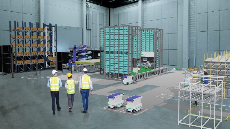
Offline programming (OLP) software is becoming an increasingly essential tool for manufacturing professionals charged with planning new robot work cells; and it’s being used for much more than developing the robot program. OLP software helps with planning and optimizing the work cell design, virtually commissioning the robot, and accelerating the time to production. It uses 3D CAD data to create a virtual model of the robot and work cell, and simulate the processes and workflows inside and outside the cell – a powerful tool for engineers and planners to evaluate trade-offs and make better decisions. OLP software provides a meaningful return on investment for many types of automation projects, by saving time, improving productivity, and helping manufacturers to identify opportunities for cost savings.
There are many approaches and strategies to OLP, and we’re not advocating for one approach over another. In this article, we’ll give you a quick and general overview of the steps in the OLP process, particularly as it applies to the planning and design of a new robot work cell. The process we’re describing is adapted from a paper published in 2012, titled “Recent progress on programming methods for industrial robots” by Z Pan, et al (1).
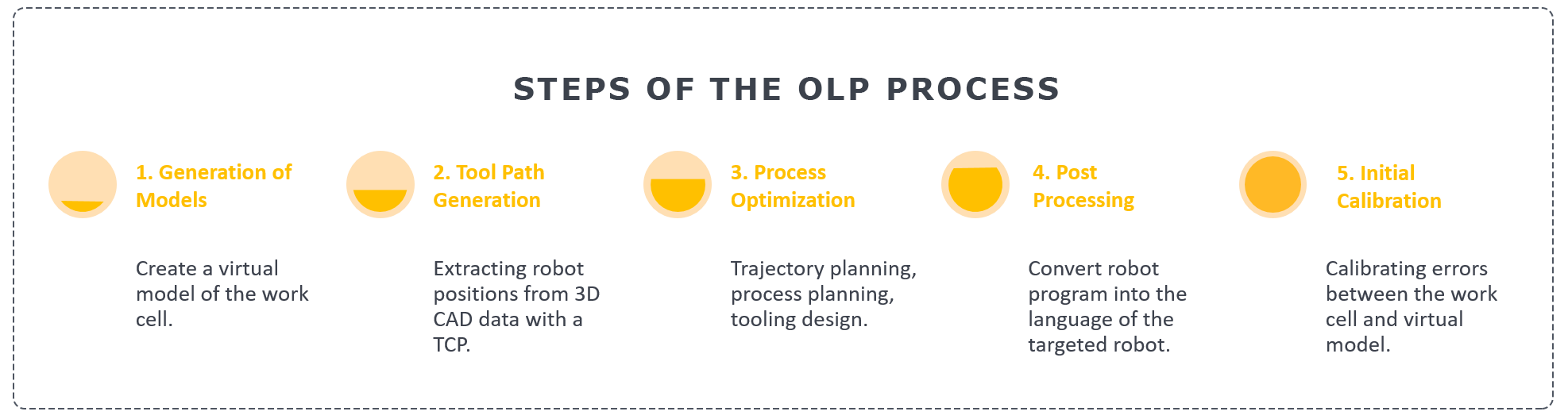
1. Generation of Models
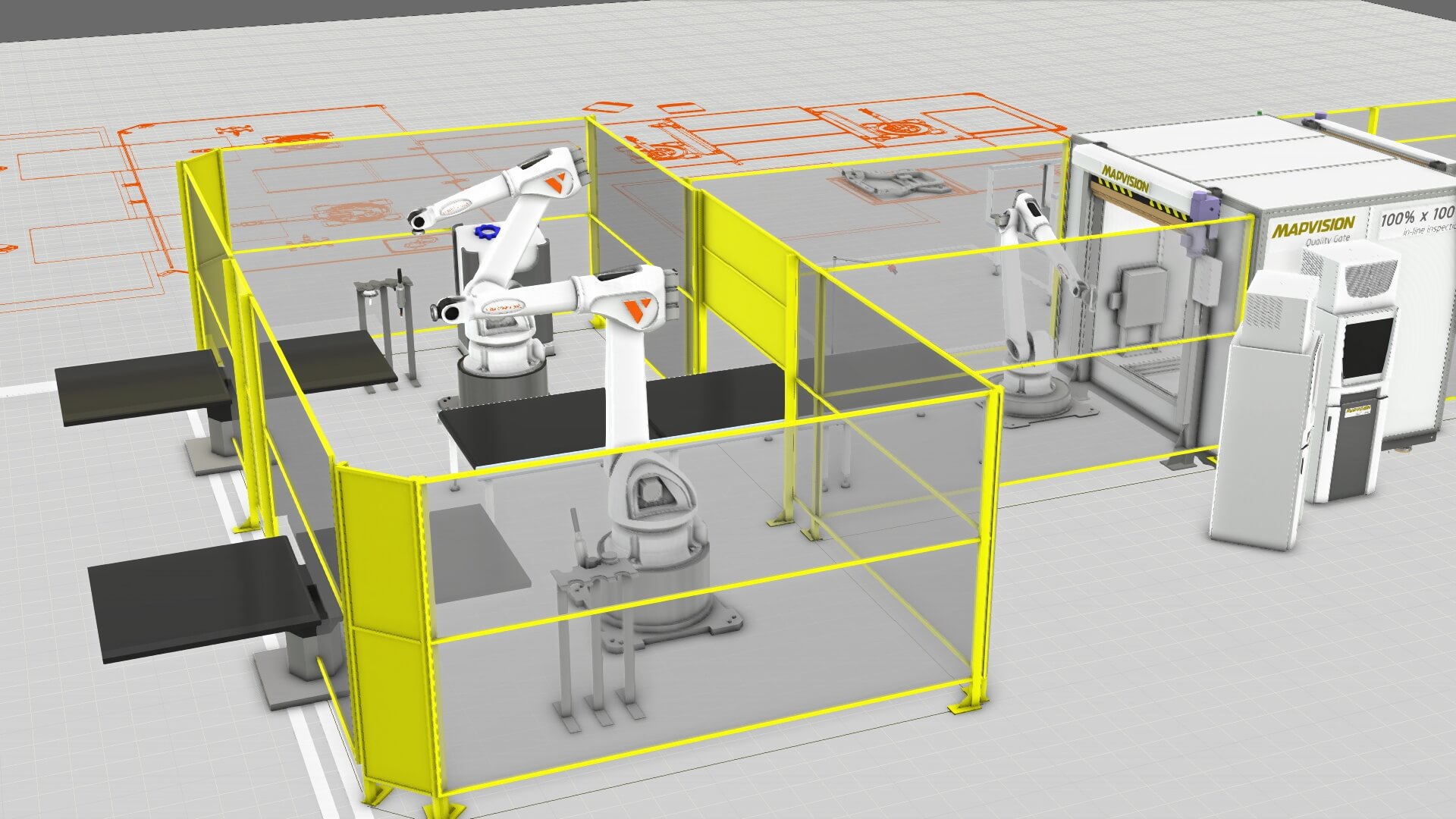
The first step to OLP is to create a virtual model of the work cell. This involves creating or obtaining 3D CAD models of the equipment, work pieces, enclosure, tools, and other resources and fixtures that will be in the work cell; and importing them into your OLP software. There may be extra steps in order to simulate resources and processes, depending on the OLP software being used. Accuracy of the models and process related information used is critical to generating a reliable simulation of the process and error-free offline program for the robots.
2. Tool Path Generation
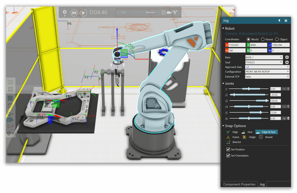
Tool path generation involves extracting robot positions from 3D CAD data with a specific tool center point – the point in relation to which all robot positioning is defined. Many OLP software packages can do this automatically, and have built-in functions to automatically generate paths from features of the CAD models, such as corners, edges, or other geometry features.
3. Process Optimization
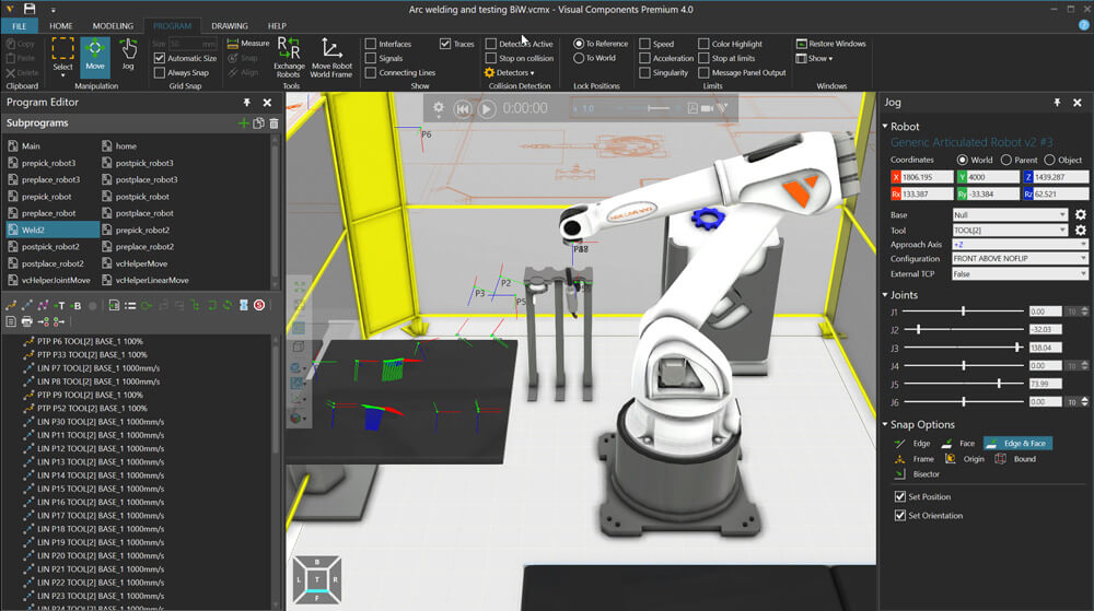
Process optimization incorporates trajectory planning, process planning, and tooling design. It’s an iterative design loop with a number of factors and tradeoffs that need to be considered, so simulation helps significantly with this process.
- Trajectory planning involves determining the best route for the robot to make, from Point A to Point B. While it might sound simple, this isn’t a trivial task; and it’s not always about planning the fastest or shortest route. Robot work cells are typically designed in compact configurations, so motions and trajectories have to be planned carefully to avoid unintended interactions between the robot and other objects in the cell. There are several factors that need to be considered, such as motion type, joint configuration / speed / acceleration, reachability, and collision detection and avoidance.
- Process planning involves planning the processes and workflow in the work cell. The major constraints for this step are budget, productivity, and quality, but there are several factors and tradeoffs that need to be considered. This step includes layout design, resource selection (including robots and other equipment), maintenance considerations, and sequence optimization.
- Tooling design involves the selection, modification, and placement of tools. This includes robotic end of arm tooling and other tools that touch the work piece, such as positioner faceplates and clamps.
4. Post Processing
After the robot program has been verified in the simulation environment, it needs to be implemented to the real robot. But first, the program must be converted into the language of the target robot. This step is called post processing. Post processors; the drivers that convert the robot programs; need to be created to perform this conversion. Post processors are specific to the robot brand, application, and other customer specific requirements for safety, usability, performance, etc. It’s rare to develop post processors from scratch; it requires lots of work and there are many companies that develop/sell them commercially; but they still require some customization for your specific application and setup. As a gross estimate, about 80% of the commands are the same for each post processor, but what changes is the local customization for each application, customer specific requirements, and special macro commands that have to be called at the beginning or end of a program.
5. Initial Calibration
Initial calibration involves calibrating errors between the work cell and virtual model, and updating the virtual model to match. The goal is to ensure the offline program is running at 100%, with no unplanned operator intervention. Calibration is performed using a tool center point on the shop floor. Depending on the application, it’s also possible to calibrate without using a tool center point; as an industrial robot can be used as its own coordinate measuring machine to determine the relative positions of critical components in the work cell.
It’s not always necessary to perform initial calibration offline; it can also be done in the production environment. For example, in robotic spot welding, there are usually around 10 to 20 points that need to be programmed in the robot. It would be much faster to have the operator calibrate the robot versus doing it offline. Similarly, in arc welding, there’s lots of variation between work pieces, and robots use vision sensors to compensate for work piece errors.
Summary
In this article, we provided a very quick and general overview of the steps in the OLP process. As you may have gathered, OLP isn’t just developing a robot program; it’s a process for designing and planning an entire robot work cell. OLP software helps manufacturers to design better production solutions by allowing them to evaluate and visualize the many requirements, constraints, and tradeoffs in the OLP process.
Visual Components Premium includes advanced features and capabilities for manufacturers and OLP specialists involved in the planning of new robot work cells. It’s used by several leading manufacturers to design and commission advanced robotic work cells and speed their time to production. The Visual Components platform is also used to power commercial OLP tools that are in use by hundreds of leading manufacturers worldwide. If you’re interested in learning more about how Visual Components can help you plan your next robot work cell, get in touch!
(1) Pan, Z., Polden, J., Larkin, N., van Duin, S. & Norrish, J. (2012). Recent progress on programming methods for industrial robots. Robotics and Computer Integrated Manufacturing, 28 (2), 87-94
Further reading
The future of automated manufacturing (and why humans still matter)
Automation in manufacturing has been evolving for decades, but its true impact isn’t in replacing people, it’s about making them more capable. We spoke with Mika Anttila, one of Visual...
Understanding digital twins in manufacturing
Digital twins go far beyond static models or simulations. They bridge the gap between virtual and physical systems, offering real-time insights and control. But with so many definitions floating around,...
Tackling the manufacturing skills shortage with simulation and robot offline programming
The manufacturing industry is grappling with a significant skills shortage, exacerbated by the pandemic and an aging workforce. According to The Manufacturing Institute, 78% of companies are concerned about this...