Automated robot programming: automated path creation in minutes
Automated robot programming reduces hours of manual work by shifting path creation and validation to the offline programming software (OLP). This article explains how automated programming works in practice, the role of the automatic path solver and how different levels of OLP automation help manufacturers scale faster with fewer programming bottlenecks.
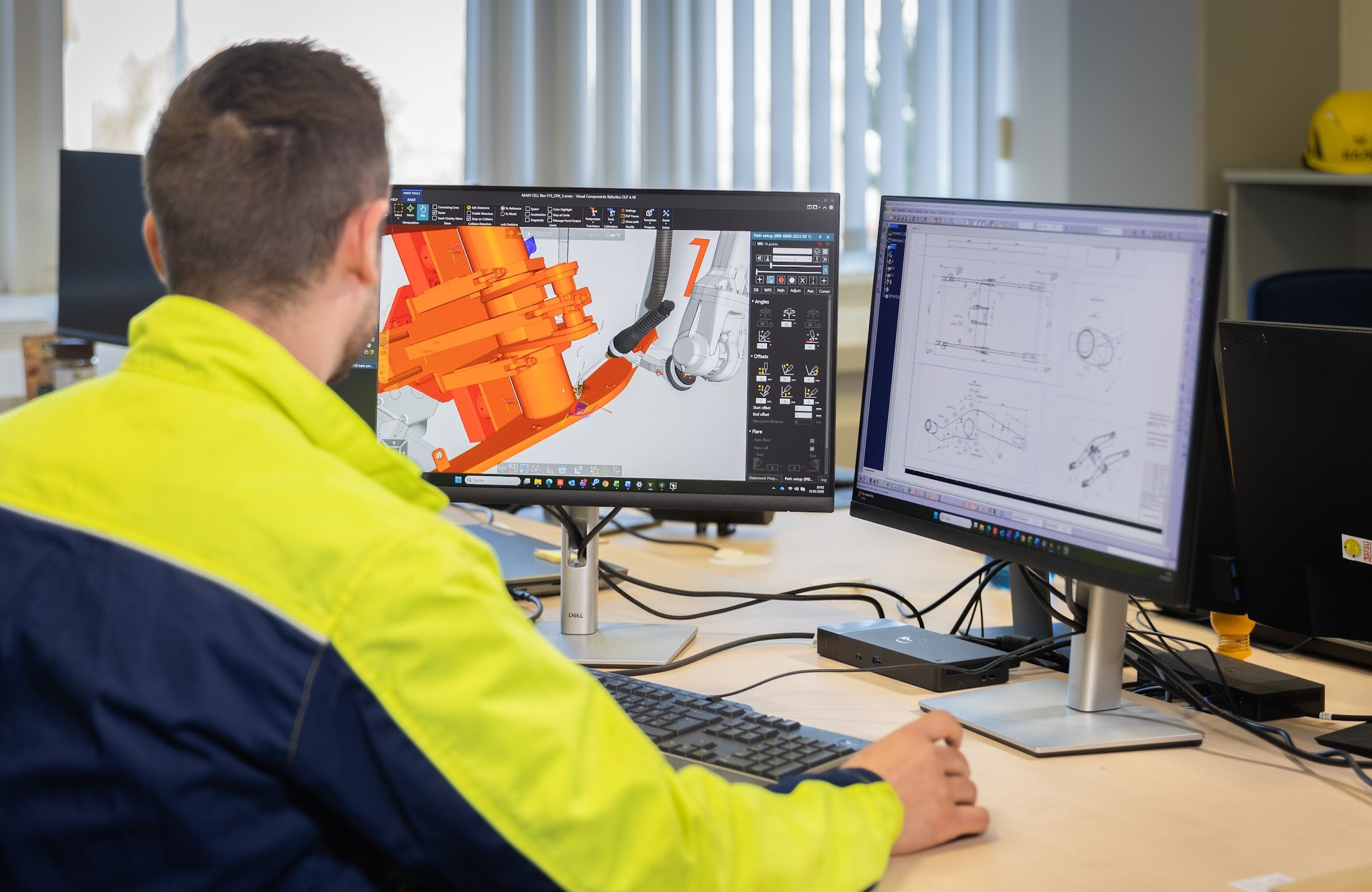
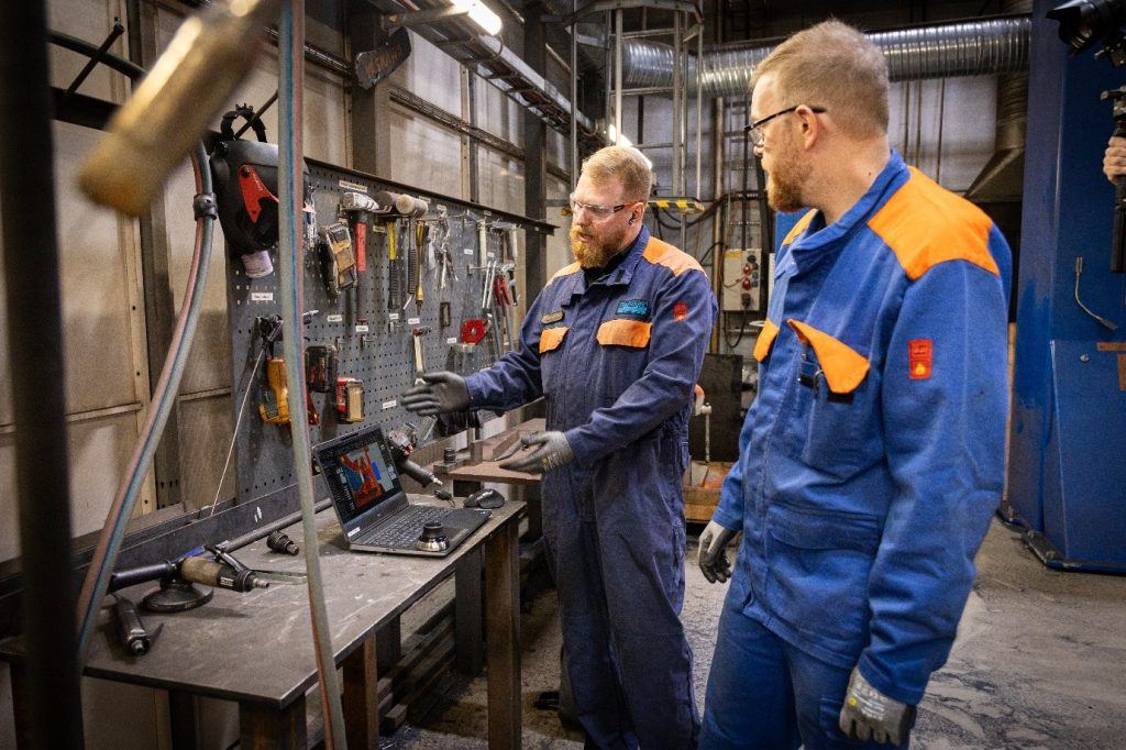
Programming industrial robots used to be slow, repetitive and tied to the shop floor. Engineers would jog robots point by point using a teach pendant and any design change meant starting over. Even moving to traditional offline programming (OLP) helps by taking the work off the shop floor, but for complex parts with hundreds of welds, it’s still time-consuming to click through every path.
Automated robot programming takes this a step further: it generates and validates robot paths with minimal human input, letting manufacturers handle higher complexity, scale production faster and reduce programming bottlenecks.
What is automated robot programming?
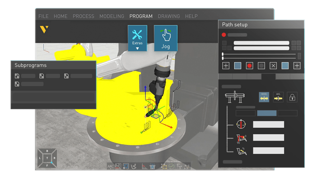
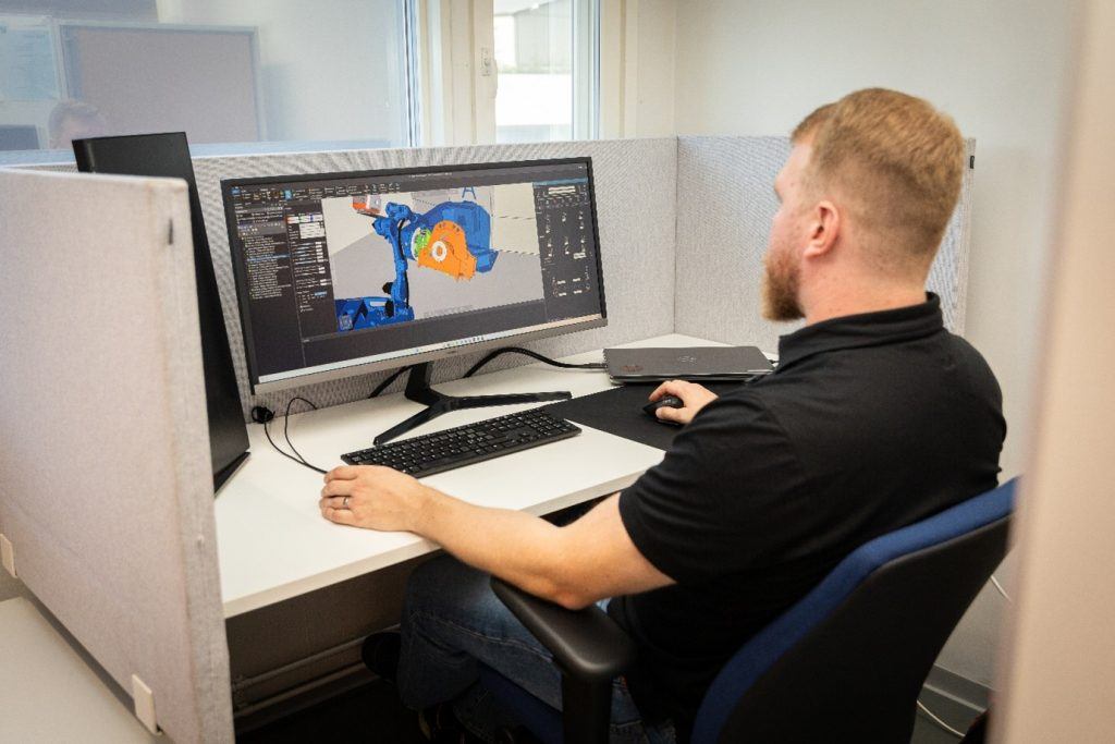
Automated robot programming generates and validates robot paths using software instead of manual teach-pendant programming. Instead of clicking through every path,, it automates much of the work while still allowing human oversight. Visual Components OLP software supports all levels of OLP automation:
One-click programming is fast path creation with minimal input — select surfaces and edges to generate robot paths from a bare 3D model. It’s the entry point to automated programming and good for getting started or handling one-off parts.
Feature-based programming applies reusable program templates to recurring features across part families. When your welding procedure specifications (WPS) are digitized in the OLP software, every operator works from the same validated parameters instead of hunting through paper binders or relying on tribal knowledge.
Model-based engineering is the highest level, where PMI flows from CAD into robot programs with minimal human intervention.
Think of it as a maturity curve: walking is teach-pendant programming, running is one-click programming and flying is fully automated model-based engineering with the solver validating paths automatically.
Across all automation levels, the automatic path solver handles the complex task of validating and fixing robot paths to avoid collisions, stay within joint limits and respect reachability constraints—whether paths are created interactively or imported from CAD.
Two phases of automated robot programming
Each automated robot programming level in OLP involves two phases.
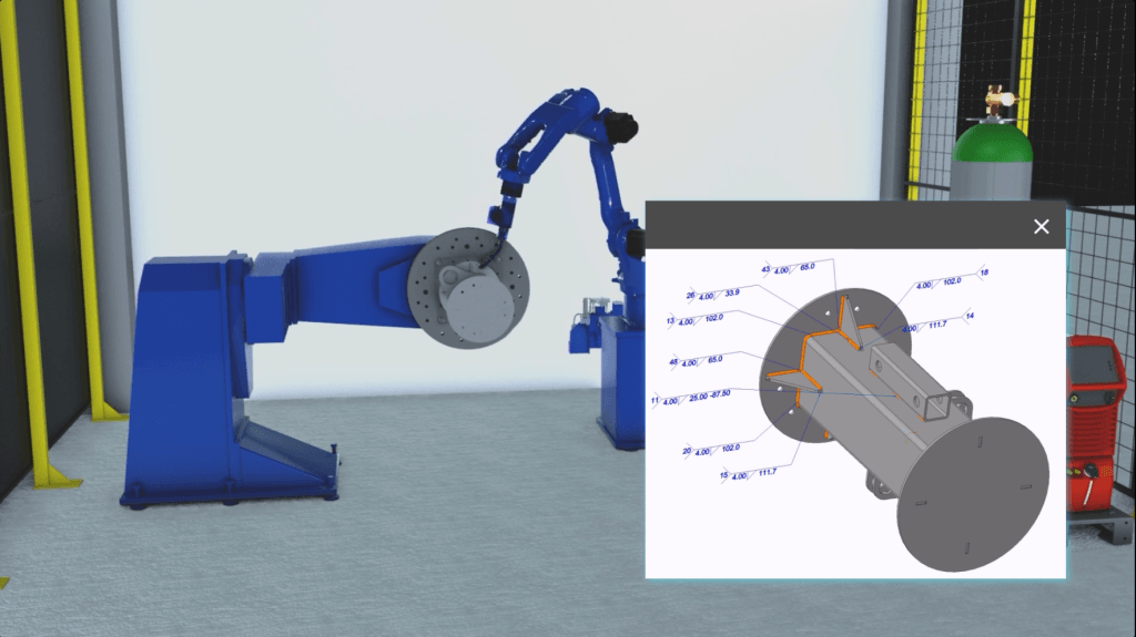
Path creation defines where the robot should go. Robot paths are generated from the 3D model, but the level of automation depends on how much manufacturing information is available and how it’s used.
At the first level of automation, one-click programming allows users to create paths by selecting surfaces and edges directly from the model. It’s fast and already a clear step up from teach-pendant programming, but paths are still defined interactively.
Feature-based programming builds on this by recognizing part features such as weld seams or holes and applying predefined manufacturing rules to generate paths automatically.
At the highest level, model-based engineering uses product manufacturing information (PMI), such as weld seam locations or cutting geometries embedded in the CAD model, to automatically create paths across the entire workpiece with minimal or no manual input.
Path validation determines whether those movements are physically possible and process-compliant. That’s where the automatic path solver comes in. The automatic path solver checks every generated path for collisions, joint-limit violations, singularities and reachability problems, then resolves path issues.
Together, these two phases remove most of the interactive robot programming step. While all three levels rely on the same path solver, the highest level delivers the biggest time savings, especially for complex parts with hundreds of seams or operations.
How the automatic path solver works in OLP
The automatic path solver ensures that robot paths are not only collision-free, but also manufacturable. It uses Visual Components OLP’s built-in collision detection to identify conflicts between the robot arm, tooling, workpiece and fixtures. When a collision is detected, the solver searches for an alternative robot joint configuration or tool orientation that avoids the obstacle, then smooths the motion to keep movement stable and continuous.
Solving process constraints, not just geometry
What sets this solver apart is that it considers process constraints:
- Welding example: Torch work angles must stay within specific ranges for proper penetration. Carbon steel is forgiving, but aluminum, stainless steel and laser welding are tighter.
- Process-specific presets: Each preset defines three bands—optimal, acceptable and maximum—to guide the solver. Multiple presets can be applied and switched automatically for MIG/MAG, TIG or cutting tools.
This depth of process knowledge comes from years of collaboration with partners like Fronius (welding power sources) and Lappeenranta University of Technology (welding research). Unlike many competing solvers, it keeps quality constraints in the loop, so fixing a collision doesn’t create new process issues.
Solution passes and retries
The solver uses a two-pass approach:
- Quick pass: Handles ~70% of collisions with simplified settings.
- Extended pass: Broader sampling for more complex collisions.
If neither pass finds a solution, the issue is usually tooling, fixturing or part design—not the software. Randomized sampling also means re-running the solver can find paths missed the first time.
How the solver works across welding, cutting and painting
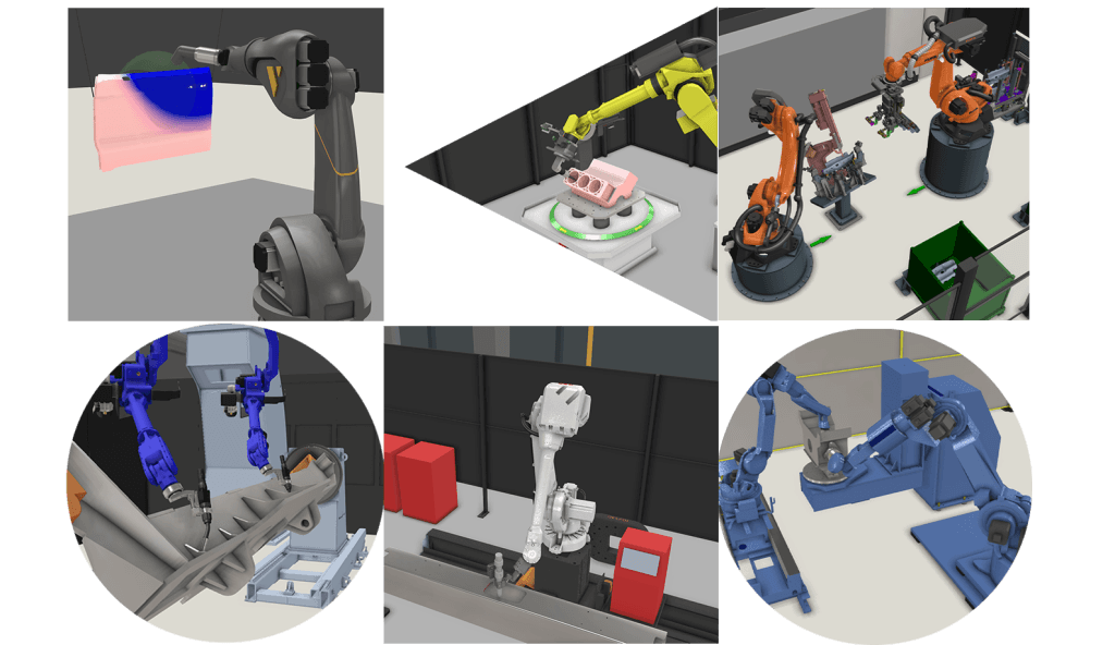
The automatic path solver is optimized for different industrial processes:
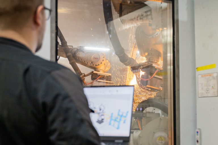
In welding, the solver handles torch work angles, push/drag angles, weave direction and material-specific tolerances. Multi-pass sequencing is automated too: define the root pass and the OLP software populates fill layers using predefined templates and optimizes the sequence to balance heat input.
Cutting benefits from blade-angle constraint management along complex 3D geometries, where approach angles need to stay within process limits throughout the path.
Painting sees fewer collision issues because spray guns work farther from the surface and painting robots typically have more degrees of freedom. The solver still resolves singularities and reachability issues, but the bigger value there is consistent perpendicularity and coverage.
The solver also handles air moves, the transitions between process paths. It guarantees collision-free travel, though it doesn’t optimize for shortest route or fastest cycle time. For high-volume automotive lines where half a second matters across hundreds of robots, third-party tools like Realtime Robotics can plug into the Visual Components environment for that kind of optimization.
When the solver can’t find a path
The solver won’t always find a solution and that’s actually useful information.
First, retry. The solver uses randomized sampling, so running it again may find a path the first attempt missed. If that doesn’t work, extend the solution time and give the algorithm more room.
Then look at your physical setup. A tool collision in a deep cavity might clear up with a longer torch that keeps the robot arm farther from the workpiece. Clamps in the wrong position are one of the most common causes of unsolvable paths in real deployments. Automated clamps that retract via I/O signals during specific program steps can help.
If nothing works, you’ve still gained something: confidence to go back to the design team. You can show them, with data from the solver, that this part isn’t manufacturable in its current form. That feedback loop prevents expensive surprises on the shop floor. In practice, these conversations tend to save more money than the robot offline programming time savings do.
What the automated programming time savings look like in practice
To measure time savings, we compare the time to create and validate production-ready robot programs—not software setup or digital twin creation.
As a broader benchmark: model-based programming takes minutes, one-click OLP takes hours, teach-pendant programming takes days or weeks. New users often build trust in the solver within a week: initial skepticism turns into surprise when a path that once took 30 minutes is resolved in two seconds, fueling appetite for more automation.
These improvements are reflected in real production environments:
Ponsse (forest machinery): Reduced programming for a large frame component from 10 days to 1 day with one-click and feature-based methods. Programs are reusable across variants, making each new model faster. Higher time savings are possible once model-based engineering is adopted.
Duun Industrier in Norway pre-programmed a complete robotic welding cell before the robot was even installed. Production started on day one maximizing the efficiency and ROI.
Sandvik: Doubled robotic welding capacity using OLP for program scaling. Modularization allows smaller projects with similar parts to reuse programs and adjust only the changed details, speeding ramp-up for new but related products.
Choosing the right level of automated programming
Which level of automated programming you should choose depends on your production environment.
If you have a small workshop with a few welds per part, one-click programming is probably faster than setting up the full model-based engineering pipeline. Same for prototyping and R&D, where you need flexibility more than speed.
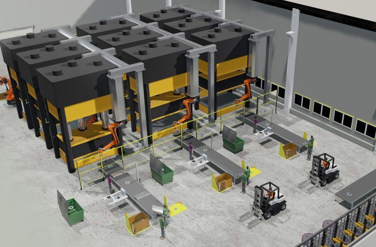
Complex multi-robot cells with large workpieces that require re-fixturing and multiple welding positions still need interactive human decisions at the path-planning level. And frequent design revisions need a validation step before each change reaches the robot. Until full PLM integration closes that gap, a person has to review.
Even in these cases, the automatic path solver still accelerates the work. You program interactively at the one-click level and let the solver handle collision resolution and path smoothing.
Where automated programming is heading
Automated programming fundamentally reduces the reliance on scarce robot programming expertise. Instead of a skilled robot programmer spending hours on each part, the OLP software does the bulk of the work and a programmer reviews the output. For manufacturers dealing with labor shortages, that’s a real multiplier.
As more PMI moves into CAD models through model-based engineering, the interactive steps keep shrinking. We’re not at fully lights-out programming yet, but the gap between “CAD file arrives” and “robot runs” is getting shorter every year.
See it in action: book a demo to see how automated robot programming can be applied to your production environment.
Frequently asked questions
Automated programming in OLP covers three levels of automation. One-click programming lets you generate robot paths by selecting surfaces and edges on a 3D model. Feature-based programming applies reusable templates to recurring part features. Model-based engineering imports product manufacturing information (PMI) directly from CAD models to generate programs with minimal human input. Across all three levels, the path solver validates programs for collisions, joint limits and reachability. For more detail on each level, see the OLP automation levels blog post.
The solver resolves collisions and singularities within individual robot programs, including configurations with external axes. Multi-robot coordination with large workpieces and re-fixturing still needs a human making interactive decisions at the planning level. The solver speeds up the work even then by handling collision resolution automatically.
Visual Components OLP is brand-agnostic and supports all major industrial robot brands through post-processors and a robot library. You can program robots from different manufacturers in the same environment.
Retry first, since the solver uses randomized sampling and may find a different solution on the next run. If that fails, extend solution time, then investigate tooling (try a different torch length), fixtures (reposition clamps) or flag the issue to the design team.
Yes. The solver uses process-specific presets with different constraint ranges for each process. Welding gets the deepest support (torch angles, material tolerances, multi-pass sequencing), followed by cutting and painting.
It uses built-in collision detection to find conflicts between the robot, tooling, workpiece and fixtures, then computes alternative configurations that avoid obstacles while staying within process-specific constraints like torch angles. Paths are smoothed so the robot doesn’t jerk around detours.
Rough benchmark: model-based automated programming takes minutes, one-click OLP takes hours, teach-pendant programming takes days. Ponsse reduced programming for large frame components from 10 days to 1 day using one-click and feature-based programming. Savings compound when programs are reused across part variants.

Further reading
Complete guide to ABB robot programming and offline programming
Master ABB robot programming with offline programming (OLP). This comprehensive guide explains how to efficiently program MultiMove synchronized welding cells, streamline the OLP workflow and choose the right software, ABB...
Optimizing manufacturing with simulation and robot offline programming
Manufacturers are increasingly relying on simulation and robot offline programming to master variant diversity, improve quality and keep cycle times predictable. This article explores how simulation, digital twins and offline...
Manufacturing simulation and robot offline programming as the foundation of digital production planning
Manufacturing simulation helps companies validate feasibility, optimize performance and reduce risk before building real systems. By combining production simulation with offline robot programming, manufacturers can test cycle times, robot reach,...