Leveraging simulation for factory layout design
Explore how discrete event simulation and digital twin technology play crucial roles during the ideation and planning phases of factory layout design. Our software simplifies the design process, providing accurate insights and highlighting the importance of visualization in streamlining communication – helping solve both existing and potential manufacturing issues.
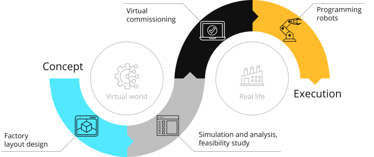
When laying out a manufacturing operation, discrete event simulation is a powerful optimization tool. It can even form the basis of a digital twin that enables virtual commissioning, avoiding potentially expensive mistakes and supporting planning and scheduling systems.
This article explains how simulation tools like Visual Components support the factory layout design process. It covers how a factory’s layout reflects manufacturing strategy, when new layouts are needed, and how to set about designing an optimized layout with the help of Visual Components. Individual sections address:
- Why layout matters and when to study it
- Defining and launching a project
- Multiple dimensions of factory layout design using Visual Components
- Additional considerations in factory layout design
Why layout matters and when to study it
A factory layout expresses a business’s manufacturing strategy. It connects each step of the sequence of operations, its constraints, and the movement and storage of materials. Layouts evolve over time and often what was optimal morphs into something less efficient and harder to manage.
The process of laying out a factory includes deciding what equipment to use, establishing the relationship of each piece to the next, and the space needed for material movement, operator access, and maintenance. It should also include simulation to determine how well the layout will meet the organization’s objectives.
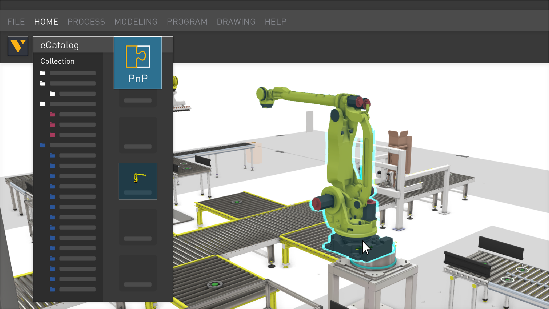
Look at just how easy it is to leverage even the basics of Visual Components to aid in this design process.
This is all done in the context of the goals management has for manufacturing. These could include making to order exclusively, using one-piece-flow principles, cellular manufacturing, or batch production. The selection and positioning of equipment determines how work will flow through the factory and the extent to which the goals are achieved.
Factory layout design takes place in two scenarios: greenfield and brownfield.
The greenfield layout scenario refers to new construction. It’s a blank sheet of paper with the opportunity to fully optimize workflows with minimal constraints. Work starts on the layout before construction is complete because this will guide the provision of services like filtered air and dust extraction. In some cases, a conceptual layout is needed even earlier as this provides the area needed for the factory plus numbers of shipping docks, material storage facilities and so on.
A brownfield scenario is where the factory layout already exists. Management might decide to review it for a number of reasons, such as a substantial change in the products or quantities being manufactured, or simply as part of an effort to increase efficiency.
There are usually many constraints in a brownfield layout design. Access roads are often fixed, the building itself is of a particular area and configuration, services are only available in some areas and there may be obstructions like columns to work around. The challenge here is to optimize the workflow within the constraints of the existing building.
Defining and launching a project
Designing a factory layout is a project and it should be treated accordingly with formal goals and a defined scope. Identify constraints, deadlines, and most importantly, the stakeholders, of which there will be many.
When defining scope and identifying constraints brownfield scenarios usually offer more challenges. The total area available is limited and may be configured in ways that are difficult or expensive to change. It may also be necessary to maintain production while areas are being refurbished and equipment relocated.
Once boundaries are established, layout planning can get underway. Given the likely large number of stakeholders, it’s usually good to begin with general concepts that provide a starting point for discussions. Planning and designing a manufacturing layout is almost always an iterative process and it’s important to allocate plenty of time for developing, presenting, and then revising options.
A challenge the designer or team frequently encounters is the difficulty of communicating how the proposed layout will work in practice. Graphical discrete event simulation such as that available from Visual Components can be a very powerful tool for showing how the new configuration will function in a wide range of scenarios.
Multiple dimensions of factory layout design using Visual Components
There are many aspects to a successful factory layout design exercise. It begins with a detailed understanding of the manufacturing process and should end with a model suitable for evaluating different production scenarios and solving specific challenges.
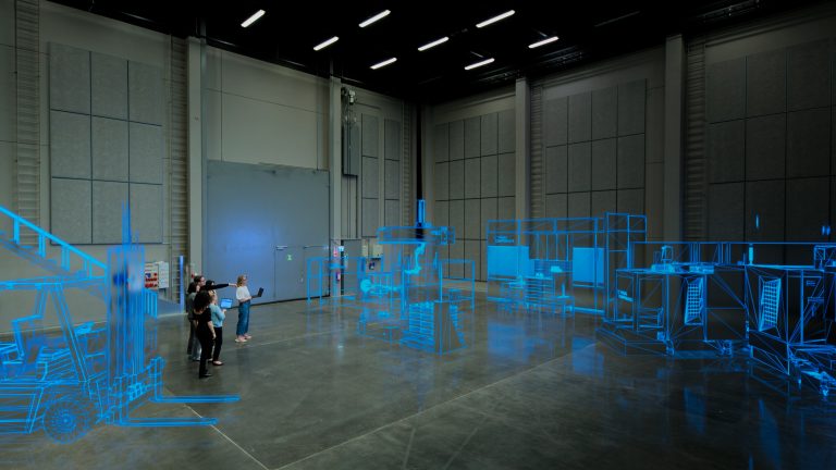
In between, there are questions of process dependencies, the granularity expected, and the speed and efficiency of the design process. Outputs include drawings showing where equipment should be placed and how services will be provided, but many manufacturers today are looking for a digital twin. This is a recent manufacturing innovation that can be used for virtual commissioning and experimentation.
In modern factories, the manufacturing process is rarely a single stream from start to finish. Product variants and requests for customization result in materials and components feeding in at various points, operations being bypassed, and different endpoints.
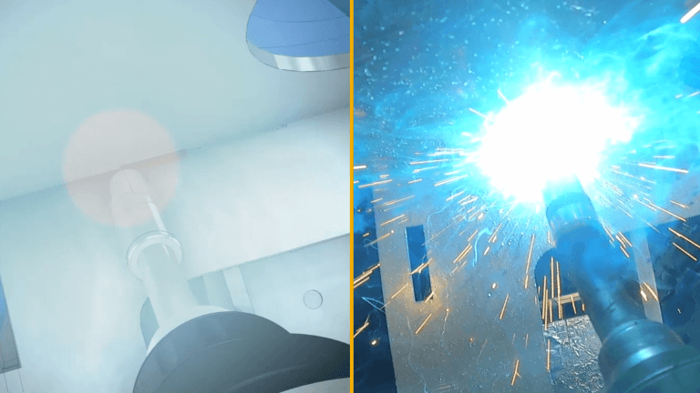
Begin by understanding these variations and developing a complete map of the process or activities being laid out. From here dependencies, both where processes should be spatially adjacent and where they might need separation, need identifying. (For example, it’s usually prudent to separate welding from painting.)
Layout work usually starts with a high-level conceptual overview. This shows how functions will be positioned relative to one another: machining next to cleaning, which is next to assembly, for example.
Having secured consensus about the concept, detailed work can get underway. This becomes progressively more granular, eventually reaching the level of automation solutions components like robots and even individual tables and workbenches.
More detail requires more work, so there is a trade-off to be made between detail and speed. This is where Visual Components helps. By using standard modules and enabling rapid layout creation, evaluation, and revision, it greatly reduces the amount of effort needed to build a digital model of the layout. (An 11-module Learning Path details how to perform manufacturing design and planning with Visual Components.)
Examples of what can be achieved with the use of Visual Components include:
- Reduced separation between robots and other machines: accurate work envelop modeling allows higher space utilization
- Optimized storage areas: if too large they can allow inventory levels to rise
- Reduced transportation distances
- Less handling
- Bottleneck identification and resolution
Additional considerations in factory layout design
Layout design is always an iterative process. There are multiple iterations in drilling-down to the level of individual pieces of equipment, and further iterations as new information becomes available. Having the right tool to model factory operations helps speed up the optimization process, enabling a conclusion to be reached faster.
Accuracy is essential if the model is to yield useful results. Thus the design team must put effort into gathering accurate numbers for operation times, dimensions, package sizes and so on. Model accuracy can be validated by running a current production schedule and verifying that results match what was achieved in the physical world. (Any deviations should be investigated and the model revised if necessary.)
An essential element of a new layout is to ensure worker safety. The layout must include space for appropriate guarding around automation solutions and hazardous processes such as those involving chemicals, even though this may compromise workflows and material handling.
A factory layout cannot be designed with CAD alone, because it is much more than the physical arrangement of machinery. The layout has to work, and this can only be established through real-time simulation. Visual Components provides a powerful tool for designing factory layouts, ensuring efficiency, accuracy, and adaptability in modern manufacturing. Contact us to learn more.
Further reading
Digital twin in manufacturing: what it is, how it works & why it matters
Learn what a digital twin in manufacturing is, how it works, and how manufacturers use digital twins to reduce risk, boost efficiency by up to 30%, and accelerate production, with...
Robot offline programming (OLP): the complete guide (with examples)
This is your complete and comprehensive guide to offline robot programming (OLP). After introducing the topic, it addresses common misconceptions, the problems it resolves, benefits, and real-life example of its...
Manufacturing simulation: bring your projects from concept to reality
Manufacturers that commit to the digital transformation inherent in Industry 4.0 will reap the rewards of higher production efficiencies and faster project execution. Together, these will drive growth and profitability...