How to plan and design a manufacturing plant layout (video examples included)
Our experts at Visual Components discuss how to plan and design a manufacturing plant layout with a simulation case. We review the benefits, process, and necessity for a high-quality plant layout in your business organization.
When it comes to running a manufacturing facility, there are a lot of things to consider. As an owner or manager, you’re probably looking for ways to speed up your process, improve your yield, and increase your profit. A well-designed plant layout can help you achieve all three goals.
When it comes to running a manufacturing facility, there are a lot of things to consider. As an owner or manager, you’re probably looking for ways to speed up your process, improve your yield, and increase your profit. Did you know that a simple plant layout can achieve all three of these goals?
Plant layouts are often overlooked, despite their potential to save significant costs.
In this piece, we’ll discuss what is meant by a plant layout, some benefits of a layout, an example, and our step-by-step process for laying out a plant.
These are the topics we’ll cover. You can also jump to the part that interests you the most
- What is a plant layout?
- What is a lean plant layout?
- What are the characteristics of a good plant layout?
- Plant layout design benefits
- Plant layout example
- Step-by-step plant layout design process
- Case: tire assembly and warehousing layout
Let’s go!
What is a plant layout?
The plant layout definition is simple: it’s a way to draw your facility’s building, equipment, and major components on paper. It’s typically done through 2D CAD (2-dimensional Computer-Aided Drafting and Design) software.
The designer will use real-world dimensions of your equipment and facility and layout a scaled model of your plant. Without using real dimensions, the final layout won’t be as helpful for your plant.
In a lot of cases, the designer will submit a final layout that allows the viewer to fly through the building, seeing the equipment in motion and observing how the process looks. Since everything is a scale model, the viewer can find out how much distance there is between equipment, for walkways, and so on.
Since it’s all done on paper, this can be done before getting equipment or before having a warehouse. It also allows the designer to change the layout as much as they’d like.
The layout includes a lot of different features:
- How product moves through your building
- Equipment
- Building floorplan
- Dimensional distances between everything
- Visualization of your process
What is a lean plant layout?
If you take the concept one step further, you can start optimizing everything. In a lean plant layout, the designer will start incorporating lean principles into the floorplan.
A big principle in lean layouts is adding sections for different operations. If your process has multiple steps, like cutting, organizing, and packing your product, then it will be broken into different physical areas.
Cutting will be done in one zone, organizing in another, and packing in a third. This also groups together the required machinery and personnel to expedite the process.
Why does this work? Material and people travel shorter distances, the layout is more compact, and everything is streamlined.
There are a lot of other concepts that go into lean principles (a lean layout). For the sake of brevity, we’ll leave it there.
What are the characteristics of a good plant layout?
Knowing whether a plant layout is good or not really depends on your operations and needs. In general, there are a few characteristics to look for:
- Effectively uses the space. One of the limiting factors in your operation is how much space you have. You can’t just invent new space, so you have to get creative with the space you have. A good plant layout effectively uses every square inch of operation space.
- Accessible design. At the end of the day, there should be enough space between items for the full floorplan to be accessible. This means that material handlers need enough space for themselves as well as the product they’re carrying around the building.
- Flexibility for future growth. Make sure that the floorplan isn’t going to constrict your operation. A lot of manufacturing plants benefit by adding a potential for 20-40% growth. This doesn’t mean that you have to predict exactly how much you’ll grow in a decade, just design with future growth in mind.
- Has your operation in mind. You need a layout that works for your individual operation. There are very few cookie-cutter solutions that fit the needs of your business — your layout is the same way. A good plant layout is specialized to what your business needs.
Put simply, a good plant layout achieves your operational goals while optimizing key parameters.
Plant layout design benefits
Why do people spend so much time putting together a plant layout? There are a number of benefits. Let’s quickly review some of the top reasons why people opt for a plant layout in their business organization.
Reduce cycle time
Cycle time is a term that quantifies how long it takes a business to make a product. It’s the combination of every process step that’s required to make your end product.
With a good plant layout, everything is set up with the operation in mind. As a result, businesses will see a reduced cycle time.
Increase operational speed
On top of an overall speed increase, you’ll find speed increases in every step of the process. This goes back to the idea of splitting your operation into different zones.
Rather than an operator walking across your warehouse to perform a task, everything will be centralized. Think of it as storing the knives next to the cutting board in your kitchen.
Maximize your square footage
Depending on where you’re located, the price of your land could be your biggest expense. Due to that fact, most people want to maximize their square footage.
With a manufacturing plant layout, you have the ability to move equipment around on paper in order to maximize your square footage.
The designer can do things like relocating, rotating, and reorienting equipment to see which option makes the most sense for your facility. Clearly, this is a lot faster and less expensive than physically changing around equipment and testing the new layout.
Visualize and tweak your operational process
Once things are laid out, it might help you to see a potential shortcut in your operation. Maybe you can save time and money by moving one step of your process to another part of the cycle.
This is highly dependent on your operation, but we’ve seen it happen in the past: a company thinks their operation is optimized until they do a plant layout and notice some shortcomings.
Maximize profits
When you combine all of these factors, you’re left with one big benefit: maximized profits. This is the major reason why a lot of businesses opt for putting together a plant layout.
You save time, space, and create more products each year. That can translate into millions in annual savings and additional revenue.
Plant layout example
To help illustrate this idea, let’s look at an example. Our team at Visual Components led the design for a company called Midea.
Here’s a case study of one of our previous clients, Midea. They’re the world’s largest producer of major appliances. Before adding a new, high-end production line, they decided to get a plant layout.
Our simulation looked at the real-world size and operational speed of their different machines. We worked closely with their team to understand how the process works, what the limiting factors were, and what kind of flow their operation had.
After we produced some rounds of layouts, we arrived at, what both parties deemed to be, the best possible arrangement. We saved their operation a lot:
- Floor space used was reduced by 10%
- Production capacity increased 10%
- Reduced product defects by 10x
- Construction schedule expedited 20%
- Total project cost savings: $879,000, roughly 15%
- Long-term labor cost reduction, operational efficiency increase, and projected profit increase
This project for Midea shows the importance of lean plant layouts. We foresee an increase in their profits year over year — this isn’t just a short-term, upfront cost saving. The future of their operation will benefit thanks to an initial plant layout.
Step-by-step plant layout design process with a case example
Curious about what the plant layout design process looks like? Here’s a step-by-step process that we typically follow for our clients. Here’s our workflow for planning and building a plant layout:
1. Understanding clients’ needs
It all starts with understanding our clients’ needs. Before a plant layout can be generated, some information about the operation needs to be explored.
This entails a few conversations going over some basics like floor space, equipment, flow, and more.
For example, our customer Firac received a clear request from their client — to automate a manual screw tightening process. Read the whole story.
2. Planning manufacturing system design
Now it’s time to start drafting. Different companies will opt for different manufacturing programs in this step.
Some companies will only provide a 2D layout with no motion included. Others will use a 3D layout that shows how the equipment will move and how the product goes through the cycle.
At Visual Components, we typically use a 2D layout for the building and add a static 3D layout on top. This overlay ensures dimensional accuracy which is paramount in making a plant layout.
3. Equipment selection
Now it’s time to select and add equipment. This will go right into our static 3D layout, so it can be changed later.
Things like the overall size, motion constraints, and equipment parameters will be inputted during this step. This is done to ensure the model is precise and accurate.
As you probably noticed from our Midea case study, the equipment physically moves and operates in our model. During this step, we’re making sure our clients get the best visual of their potential layout.
To help our clients save time on equipment selection, we offer ready-made components. Visual Components eCatalog has a library of virtual models of robots, machines, and equipment from dozens of leading brands in industrial automation. We have over 1,500 pre-defined and ready-to-use components, to be exact.
4. Layout design
Once the equipment is selected, the designer can start moving around components. This is part of the optimization process where items are moved around until they’re in the perfect place.
Since the equipment and building are already drawn on the computer, this step is more of a “drag and drop” process. On the computer, the designer will move around equipment, change its orientation, and find the best place for the physical pieces.
Jump to 2:34-5:50 in the video below to see how it works in practice.
5. Define the flow
In step 5, we’ll start optimizing the flow. There are three major parts of this step:
- Defining the products
- Defining the processes
- Defining the process flow
There’s some overlap between this and the first step on the list. However, this step focuses on optimizing everything from a layout perspective.
This might mean changing the location of equipment, storage, and walkways to improve the overall process.
The flow is how the material cycle looks in your operation. In other words, when you trace the product from raw material to shipment, that’s the flow.
Jump to 6:43-9:22 in the same video below to see how it works in practice.
6. Simulation
With all of these parameters in mind, our team is ready to put together a simulation. The simulation will show the material and how it physically moves down the line.
A simulation is a 3D video that shows a flyby through your facility. It shows how the equipment and product move throughout. The Midea video discussed earlier is a great example of a simulation that our team makes.
However, this isn’t the final stage. Part of the simulation entails finding bottlenecks. This is where your operation is slowing down and hurting the production speed.
After finding a bottleneck, our team will work to alleviate them. Removing even one bottleneck in your operation can result in a huge performance improvement.
Some of our design software comes with plant layout analysis that aids us in targeting and alleviating these bottlenecks. This is another benefit of using computer-based plant layouts.
Read more: Manufacturing simulation: how it works and why you should do it?
7. Modify And Validate the Changes
The final stage is all about making changes to improve the design. We typically target metrics when it comes to the use of space, operation cycle time, and the ability for product defects.
These changes result in faster speeds and more room for profit within your business on an annual scale.
If this layout is done before construction, you’ll also find some construction cost savings built into this step.
The validation stage involves our clients and getting valuable feedback from you.
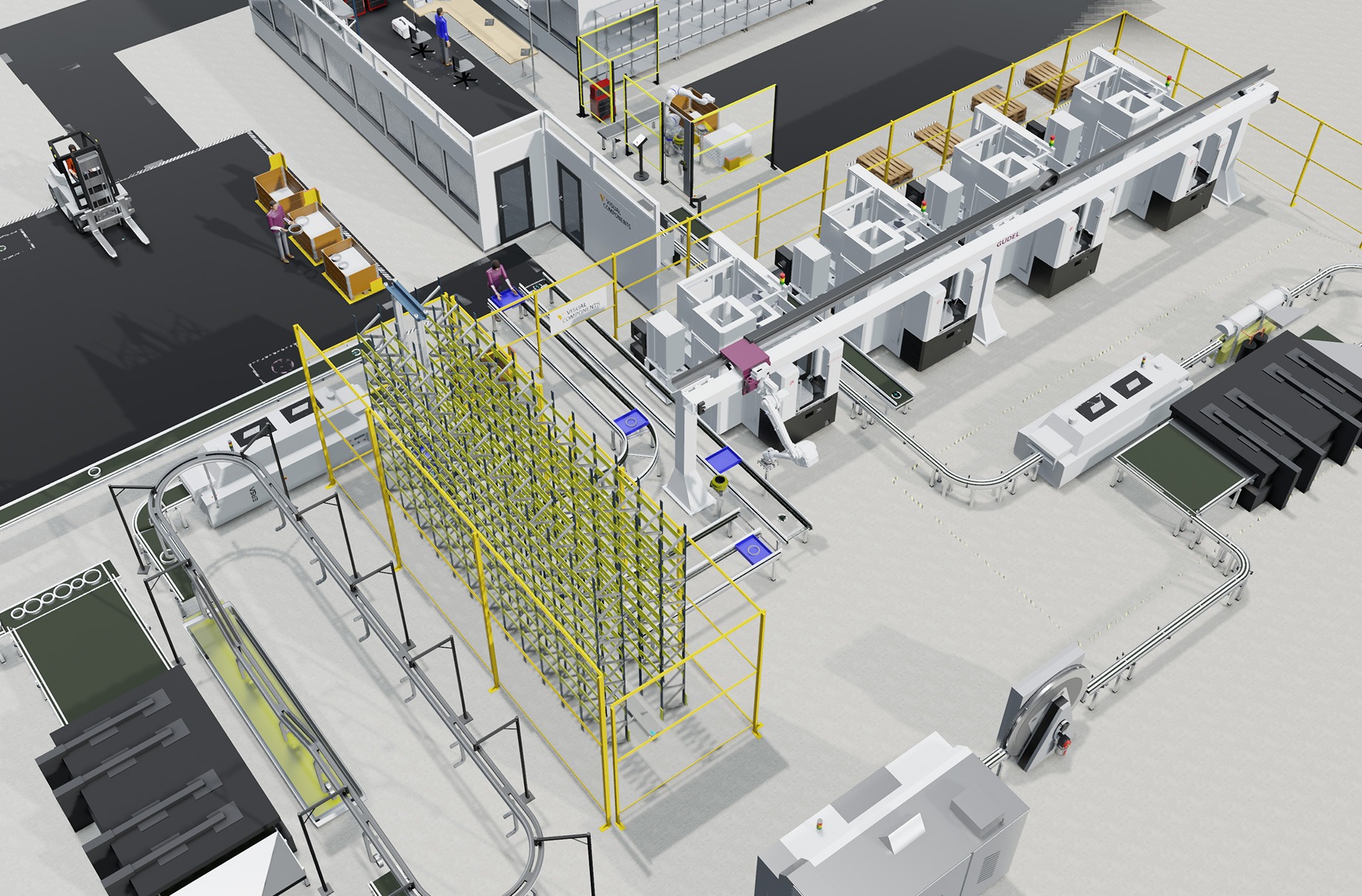
Case: Tire assembly and warehousing layout
Let’s discuss a case where the task was to design, simulate, analyze and optimize a manufacturing and warehousing system based on predefined production and layout goals.
This case is about a tire assembly and warehousing facility that is capable of handling a certain number of tires before they are supplied to a downstream assembly line. We can assume that the downstream is a car manufacturing plant.
Products and product variants
The product that we had to work with in this case was tires however there were many product variants.
First, we had three tires types meaning tires in three different materials.
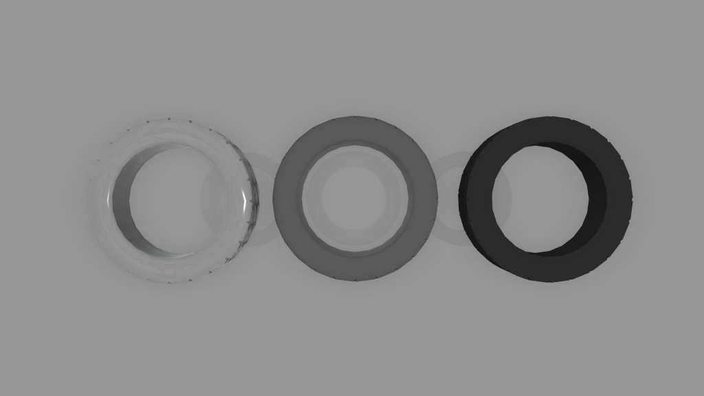
Next, we had five tire sizes in the three tire types. These sizes are represented in different colors of tire rims.
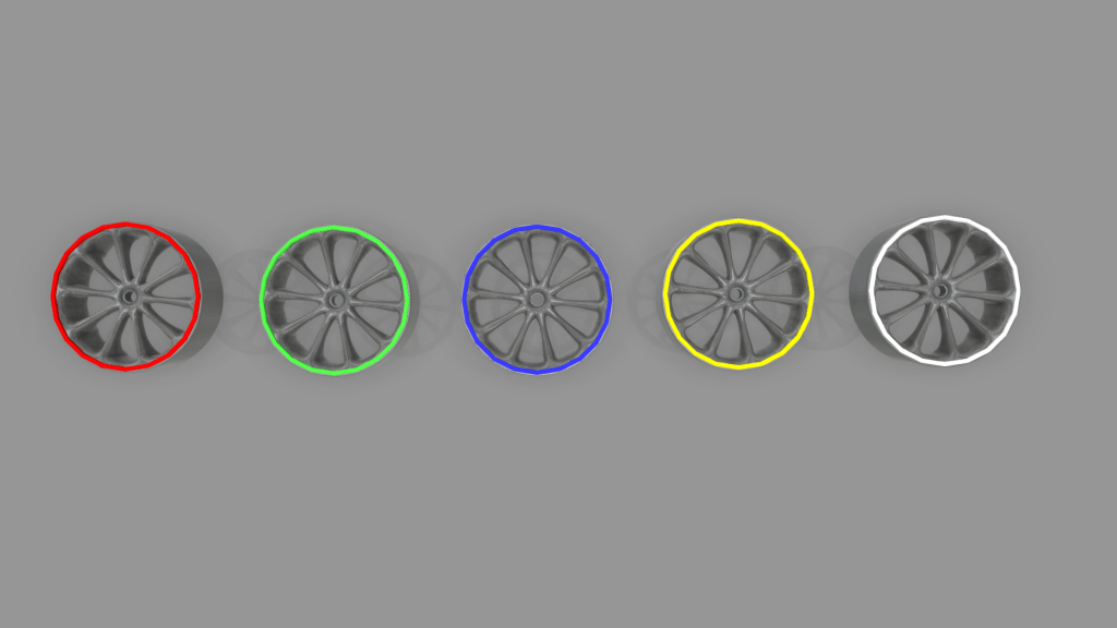
So including all the product variants, we had to design a system that could handle 15 different tires.
Production goals
Once the products and product variants were clear, the next step was to evaluate the pre-defined goals. Here’s the list of the production goals that we had to meet,
- The customer needed a setup that was capable of handling all these tires in batches of 4.
- The downstream assembly required that this tire plant could supply 720 tires per hour regardless of how many it can store. The main objective was to have a functional system that provides uninterrupted supply to the downstream assembly regardless of how many tires it could store.
- Since we were working with batches of 4, 720 tires per hour meant that the goal was to supply 3 sets of tires per minute.
Layout goals
Based on the production goals, there were also some layout goals,
- There must be enough buffer to recover from possible machine downtime.
- There must be enough warehouse to store tires for 5 hours of production meaning 900 sets in 5 hours and they must be available at all times to ensure any downtime does not interrupt the downstream supply.
- Also, in addition to storage, we needed to ensure that we had enough conveyor capacity to handle this amount and variety of products.
Layout overview and functionality
Their layout was then designed based on the given production and layout goals. Here is a video for a closer look at the layout design and functionality of different sections,
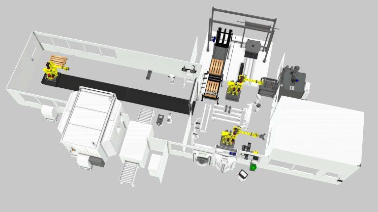
1. The tire types are fed to the robot cell as a batch of 4.
2. Next, Tire rims which represent different sizes of the tires are incoming through conveyors behind the robot cell.
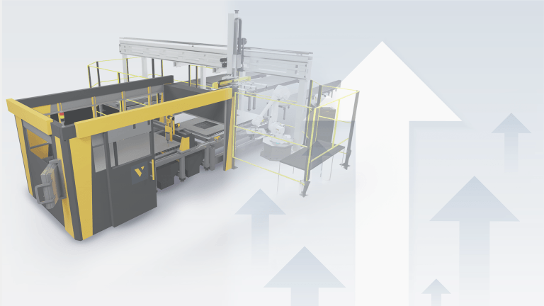
3. The robot cell is designed with 4 assembly lines. Each of these has a Yaskawa HP20RD robot on top of a smart pedestal with a tire tool. This tire tool helps to pick the tire type, lubricate it and assemble it with the rim.
4. Once Assembled, these tires go through a different set of machines where they are fixed and balanced before they are ready to be stored in the warehouse.
5. The tires are then sent towards the warehousing side with five storage sections, one for each tire size and four cartesian robots.
6. Each of these robots has certain tasks assigned to them shortly explained here,
- The first red cartesian robot sorts the tires by sizes onto their specific conveyors
- The second dark grey cartesian robot picks one stack of tires at a time and places them in their relevant tire size storage section.
- The third dark grey cartesian robot with beige pillars stores the tires by their sizes in the storage section and also supplies the sets forward when needed.
- The fourth steel-blue robot that is closer to the entrance of the warehousing collects the supplied stacks of tires released by the previous robot and places them in the rack. These racks are then picked and stored by the forklift in the next storage area.
7. From the last storage, the tires are then supplied to the downstream assembly as they’re needed.
Performance evaluation of the designed systems
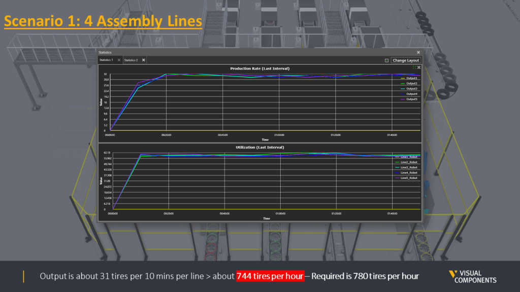
Initially, two scenarios were designed and their simulation performance was evaluated.
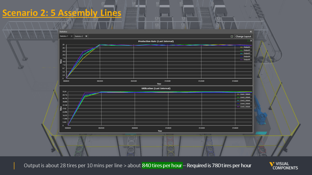
The first scenario consisted of 4 robot assembly lines.
The second one had 5 robots assembly lines.
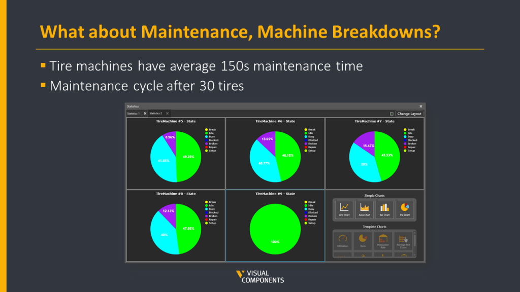
Later, we realized that machine breakdowns had not been taken into account in the first two scenarios. Machine breakdowns could be due to many reasons but the most common reason for a production stoppage is usually Maintenance. So, the Maintenance times or Mean Time Between Failures (MTBF) averaging 150 seconds were added to the machines in the robot cell. Also, the maintenance cycle was defined which meant the machine maintenance had to be carried out after every 30 tires were produced.
After these metrics were clear and defined, two more scenarios were built, basically, the same and 1st and 2nd scenarios but now with MTBF values included.
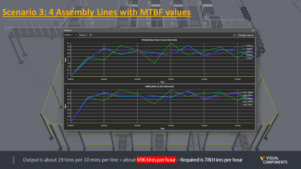
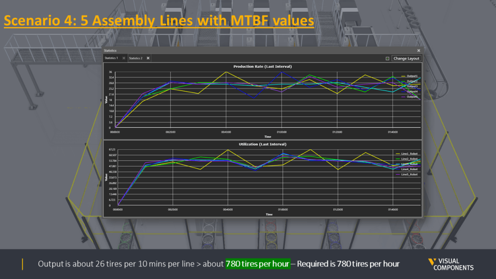
Overall, four scenarios were designed and simulated. Here is the summary of all scenarios with their production output.
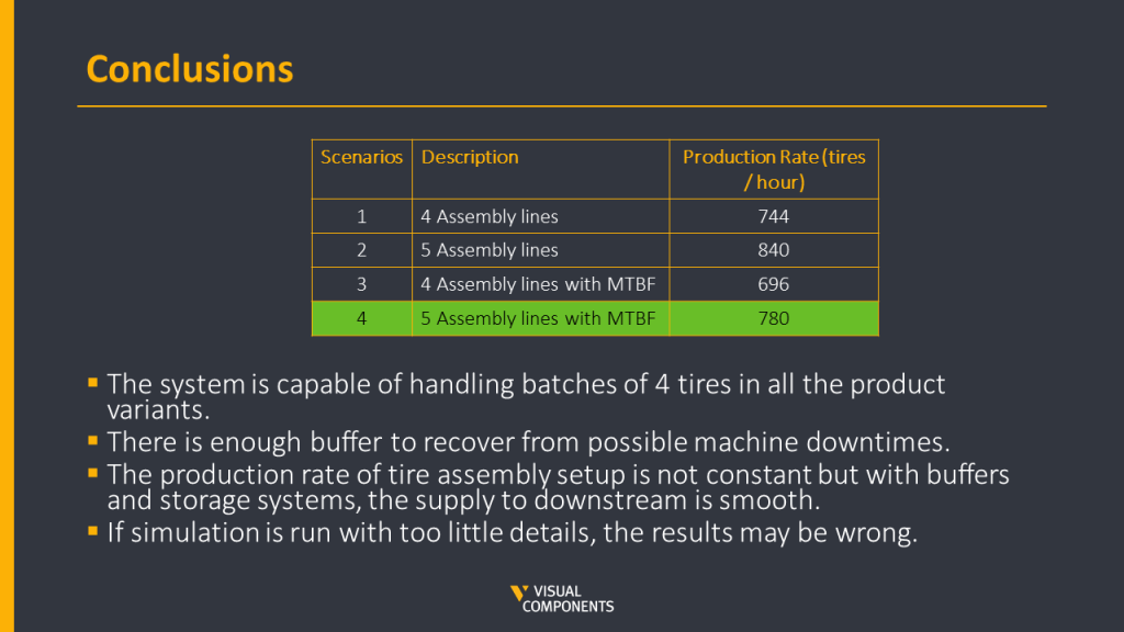
The difference in the production output is quite clear between scenarios where MTBF values were not considered and once they were. Based on the scenarios, it was safe to say that Scenario four with five assembly lines was able to generate the required goal of 780 tires per hour. This scenario was then locked as the final design for this case.
Summary of case results
Some important conclusions of this case were,
- The designed system was capable of handling batches of four tires in all the product variants.
- There was enough buffer to recover from possible machine downtimes.
- The production rate of tire assembly was not constant after the maintenance times were added but with enough buffers and storage systems, the supply to downstream was smooth.
- The last but one of the most important lessons to learn from this case was if the simulation is run with too few details, the results may be wrong like the clear difference between the production outputs in the first two scenarios compared to the last two.
Conclusion
We just reviewed how to plan and design a manufacturing plant layout. Now, you should know the benefits and process that goes into making a layout for your plant. With Visual Components, designing a plant layout is more logical, visual, and easier to do. Contact us today to get started. We’ll show you how your operation can save time and money thanks to our services.
Curious to learn more on the topic? Be sure to download our eBook about planning and optimizing your manufacturing plant layout.
Further reading
Boosting production line efficiency: a guide on improving production output
Production efficiency is the cornerstone of success in manufacturing. It measures the effectiveness of resource utilization in the manufacturing process, aiming to maximize output while minimizing costs and waste. The...
An introduction to virtual commissioning
Virtual commissioning is reshaping the manufacturing landscape by employing computer simulations for testing and optimizing production systems before they're physically built. This approach not only simplifies the setup process and...
Are manufacturers really ready for the digital era? (survey results)
Legacy equipment and outdated practices can seem like relics from another age, especially as the world zooms ahead with digital innovations. Yet, they're more prevalent in the manufacturing sector than...