Comprehensive guide to input data for 3D manufacturing simulation (examples included)
If you’re new to 3D manufacturing simulation, you’re in the right place. This comprehensive guide will help you understand the essential input data needed to create effective simulation models. Whether you’re optimizing your factory, building new concepts, or conducting virtual commissioning, the right input data is crucial for achieving accurate and useful results. Let’s explore the depths of what you need to know to get started.
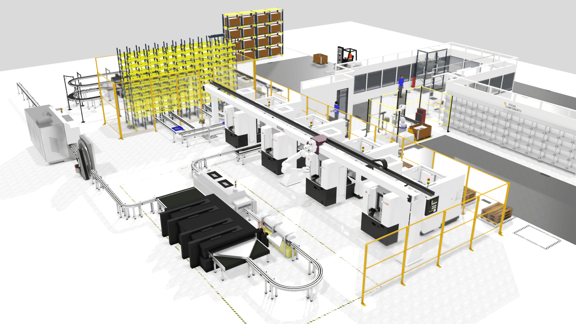
Understanding input data for simulation
The quality of your simulation outcomes is directly related to the quality of the input data you provide. Think of your input data as the foundation of a building; the stronger the foundation, the more robust the structure. In simulation, better input data typically results in more reliable and insightful outcomes. However, data requirements can vary significantly depending on your specific project, industry, and production environment.
Please note that all examples of input data laid out in this blog post are hypothetical. You will need to tailor your data collection and preparation processes to suit the unique needs of your project.
Read more: What is manufacturing simulation and how does it work?
Types of input data
To give you a better understanding, let’s break down the common categories of input data that can enhance your manufacturing simulation projects:
1. Layout configuration and placement
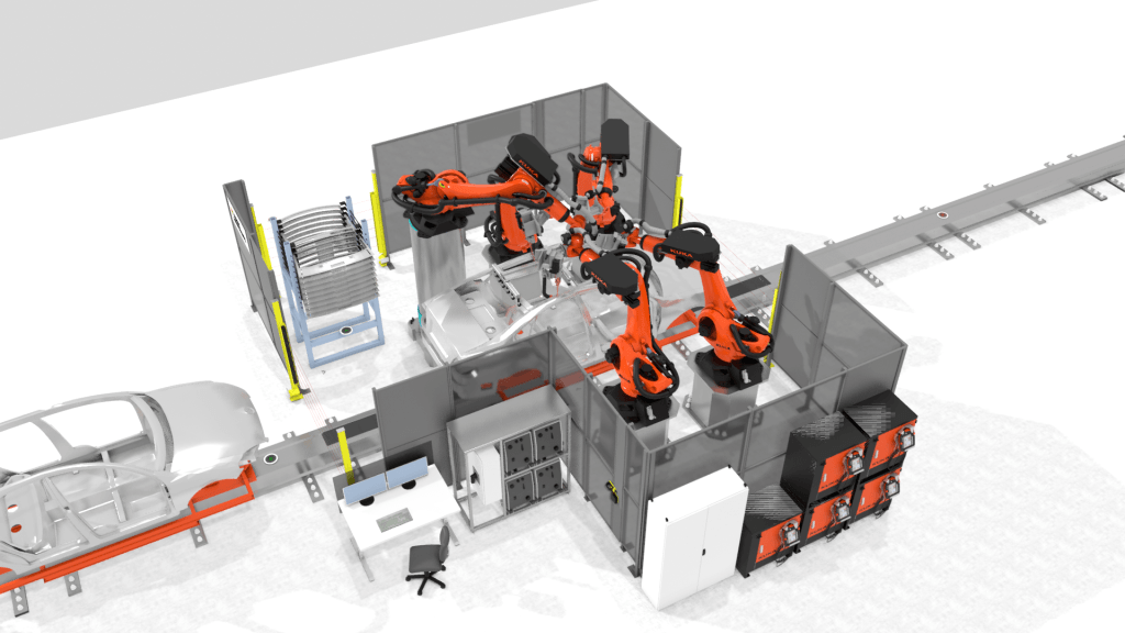
A crucial aspect of any simulation model is the layout configuration and placement of various elements within the manufacturing facility. This involves:
- Physical layout: Details about the facility’s physical layout, including the locations of machines, their dimensions, storage areas, and workstations. This data helps in accurately mapping out the factory floor within the simulation.
- Equipment choices: Information about the types of robots, mobile robots (AGVs), machines, and other equipment you plan to use. Knowing whether you will use fully automated, hybrid, or human-operated systems is also essential.
2. Factory material flow
Understanding the flow of materials through your factory is vital for an accurate simulation. This includes:
- Process routing: The sequence of operations needed to manufacture a product, including the machines and workstations involved. This helps in understanding the workflow and identifying potential bottlenecks.
- Production order schedule: Details on batch sizes, assembly order, and the flow of different product types within the factory. This data is crucial for planning and optimizing production schedules.
- Custom component properties: Information on how your custom components (e.g., machines, AGVs, or conveyors) operate, such as speeds, set-up times, and other relevant details. Knowing these properties helps in simulating timing and coordination across production stages. Visual Components also provides thousands of industry-standard components (robots, AGVs, conveyors), which already include such data from the equipment manufacturers.
3. Machine or process-specific data
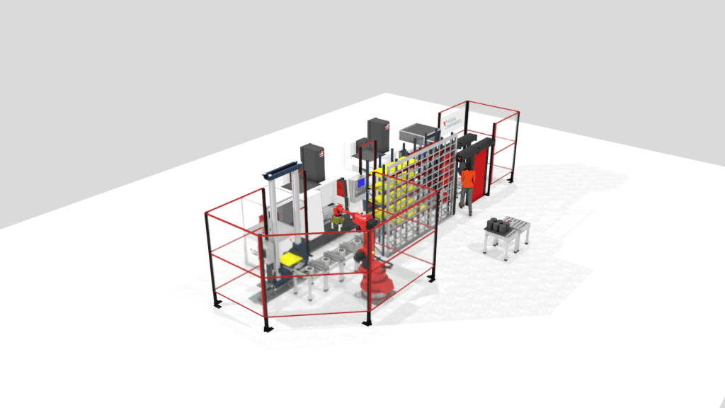
Each machine or process within your factory has specific data that can impact the simulation:
- Machine breakdown occurrence: Historical data on Mean-Time-To-Repair (MTTR) and Mean-Time-To-Failure (MTBF) for machines or workstations. This data helps in simulating machine reliability and maintenance needs.
- Buffer capacities: Information on where buffer inventories are located and their capacities. This helps in managing inventory and ensuring smooth production flow.
- Cycle times: Cycle times for individual machines or processes, which may vary by product type. This data is essential for accurate production scheduling.
- Defect rates: Historical data on machine defects. This helps in simulating quality control processes and identifying areas for improvement.
- Set-up times: Time required to set up machines when changing product types. This is crucial for planning production changes and minimizing downtime.
4. Staff in the production facility
Human resources are an integral part of the manufacturing process. Relevant data includes:
- Available resources: The number of machine operators, maintenance staff, and quality inspectors available, and their shift schedules. This helps in planning labor requirements and shifts.
- Skills of resources: Skill sets of operators, such as welding or assembly expertise. This data helps in assigning the right tasks to the right personnel.
5. Product data
Product-specific data is also critical for simulation:
- Product assembly data (BOM): Information on the steps required to assemble products, the order of these steps, and the raw materials needed. This helps in simulating the assembly process accurately.
6. CAD data
Visual Components excels in visual simulations, and CAD data is essential for this:
- Custom CAD data: Data for custom machines, robots, and products to simulate the visual aspects of the production facility accurately.
- Industry standard components: Access to a catalogue of pre-modeled components like robots, mobile robots, conveyors, and buffer systems. These components are ready to be integrated into your simulation.
Check out our Supported CAD files page to see what file formats are compatible with our platform.
Use cases and example projects
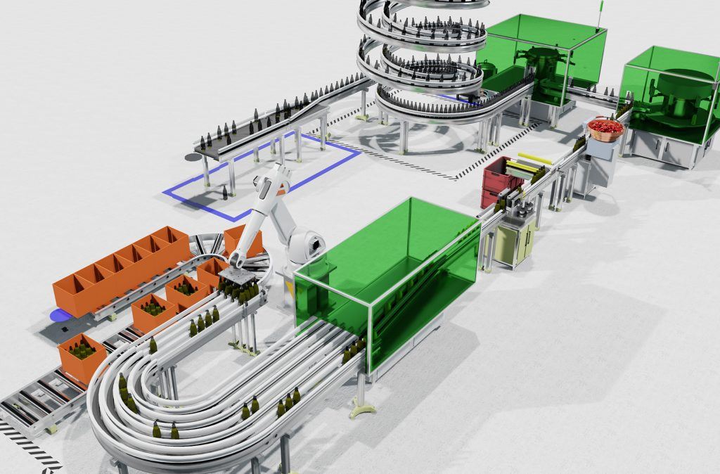
Now that we have a clear understanding of the different types of input data, let’s explore some specific use cases and example projects to see how this data is applied in real-world scenarios.
Optimization of your factory
When optimizing your factory, the objective might be to improve throughput, reduce cycle times, analyze bottlenecks, or enhance resource utilization. Here’s an example:
Example project: High-volume antenna production
In this project, the goal was to optimize an existing antenna production layout. The key questions were:
- How much does reducing machine breakdown occurrence affect production performance?
- What is the optimum number of pallets in a closed-loop conveyor system?
To achieve this, the following input data was necessary:
- Historical data on Mean-Time-To-Repair (MTTR) and Mean-Time-To-Failure (MTBF).
- Machine and product-specific cycle times.
- Set-up times between various product types.
- 2D sketches for component placement.
- 3D CAD models for products, machines, and other components.
- Conveyor speeds.
- Historical production output data to validate the simulation results.
By simulating these factors, the project aimed to optimize production output, measured in antenna units per eight-hour shift.
Building concepts or as a sales tool
Creating new system concepts or demonstrating solutions to potential customers involves different data requirements:
Example project: Machine builder sales demo
In this project, the customer wanted to provide a simple demo of their machine equipment, using a robot and a workbench. The required data included:
- CAD data of the machine.
- CAD data of the workbench.
- The chosen robot model for the layout.
For concept building or sales tool projects, typical data requirements are layout information, equipment choices, product movement within the factory, and custom CAD data.
Virtual commissioning and connectivity
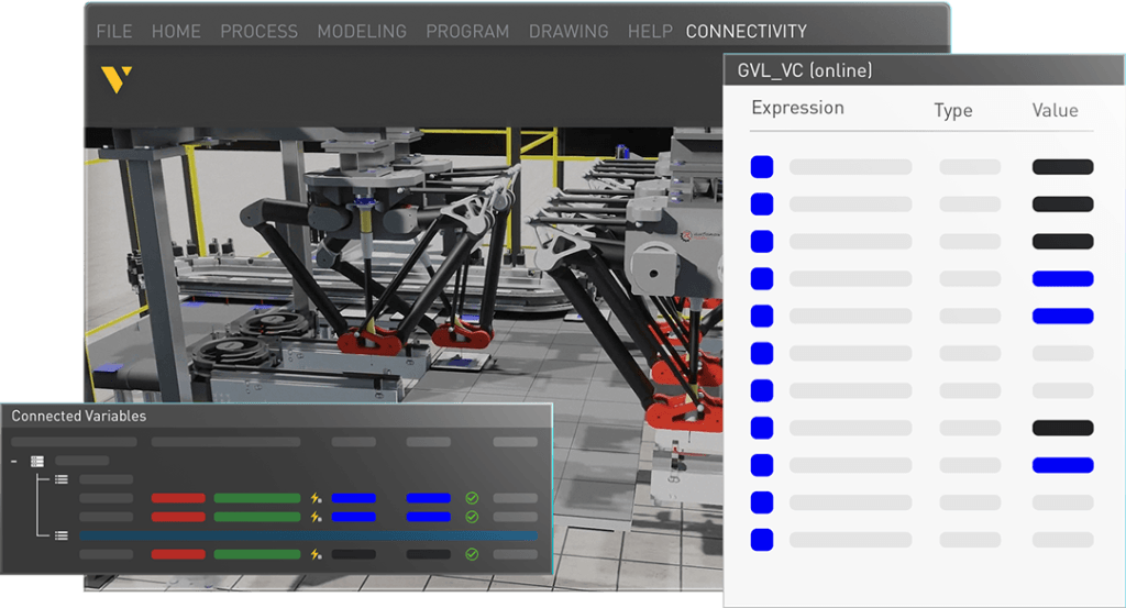
Virtual commissioning involves validating real production equipment or running a digital shadow of the factory. Important data includes:
Signal mapping, joint variables, and I/O interface mapping: Understanding how signals, robot joint variables, and interfaces between components are mapped is crucial for ensuring compatibility and functionality in the simulation.
Example project: Kawasaki virtual commissioning
In this project, the focus was on commissioning and validating the production equipment using Visual Components. The key data required included:
- Signal mapping: Understanding which signals carry out which behaviors so that when connecting equipment to Visual Components, the signals can be correctly matched. This is crucial for modeling components accurately.
- Joint variables: Data on robot joint variables to ensure accurate simulation of robot movements. For example, knowing which joint variable corresponds to a joint inside the simulation.
- I/O interface mapping: Details on how interfaces between robots and other components (e.g., grippers) are mapped. This is essential for ensuring compatibility and functionality in the simulation.
By accurately modeling these components and their interactions, the digital model effectively represents the physical system, allowing for thorough testing and validation before actual commissioning.
Conclusion
This comprehensive guide has provided an overview of the input data required for effective simulation models in Visual Components. By understanding and utilizing the appropriate data for your specific use case, you can significantly enhance your simulation outcomes. The type and extent of data needed will vary based on your industry and production environment, but this flexible framework will help you identify and collect the pertinent information for successful simulation projects.
Start your simulation journey with confidence, and harness the power of Visual Components to optimize, innovate, and validate your manufacturing processes! With the right input data, you can transform your ideas into reality, streamline operations, and achieve greater efficiency in your manufacturing endeavors. Contact us to learn more.
Further reading
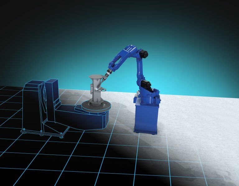
Next-level robot offline programming automation with model-based engineering
Explore how model-based engineering enables the next level of robot offline programming automation by connecting design and manufacturing through model-based definition. With validated manufacturing data exported via Capvidia tools to...
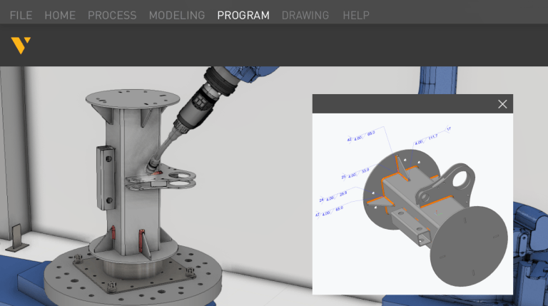
Automating robot offline programming with Visual Components OLP software
From one-click programming to fully automated use of model-based definition (MBD), Visual Components OLP software leverages product manufacturing information (PMI) to streamline workflows, eliminate manual robot programming, reduce errors and...
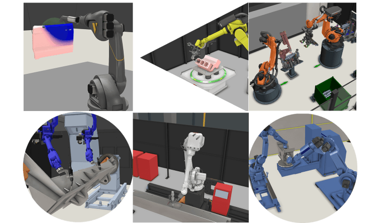
Robot programming for industrial processes with Visual Components OLP software
Robot programming is advancing with offline programming, enabling manufacturers to optimize robotic tasks virtually without disrupting production. This minimizes downtime, improves accuracy and streamlines processes like welding, spraying, processing and...