Introducing Visual Components 4.4
Visual Components is a more powerful simulation solution than ever before with the release of version 4.4 that offers exciting features for virtual commissioning, faster simulation setups, and a more streamlined experience.
Visual Components 4.4 is an exciting product release for all of you connected to the manufacturing business. Our product team is thrilled to share new features that make it easier for you to design and visualize the digital twins and use these simulation models for the virtual commissioning of your projects. If you work with automation projects, connecting to the Fanuc robot controller directly through Visual Components will streamline your robot programming and commissioning tasks by offering you all the simulation essentials in one place with higher accuracy. While we’re at saving time, you can now convert your 2D drawings from Autodesk to 3D layouts faster giving you a head start over cases where you’ve got to design from scratch. We are committed to helping you plan your systems better.
Read more about the new features in the next sections,
Check out this short video to see what’s new in Visual Components 4.4!
What’s New
More Powerful Virtual Commissioning Solution
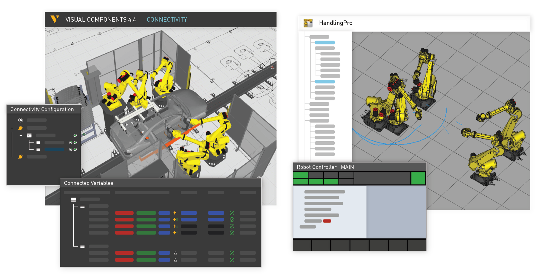
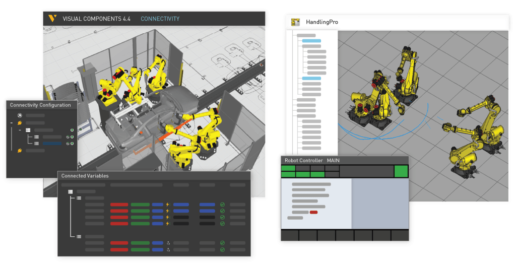
Visual Components is a more powerful simulation solution for visualizing digital twins and for virtual commissioning applications. You can program your Fanuc robots and connect to their controllers directly through Visual Components. Whether you wish to verify the accuracy of programs, check proof of process, remotely monitor your robots, or any other use case, Visual Components is the complete robotics solution for all your needs.
Faster Simulation Setups
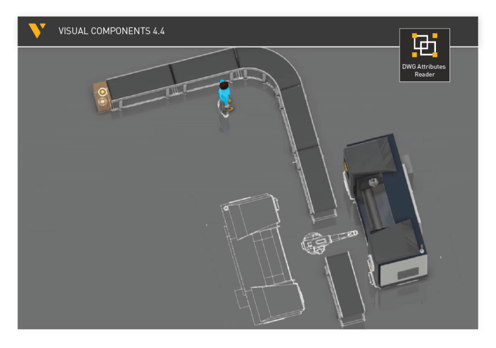
Setting up simulations is much faster. Convert your 2D drawings quickly into 3D layouts using the CAD Attribute Reader add-on and save time from layout design work. Design your assembly lines faster with our Process Modeling APIs. The open architecture also allows you to import your scripts easily to define or customize component properties and quick execution of various tasks.
DWG Block Reader video tutorial
CAD Attribute Reader Example add-on
More Streamlined Workflow
New improvements in robot programming and connectivity offer you a more streamlined user experience, simplify the workflow, and more possibilities in robot programming and IO configuration to simulate, emulate and plan your systems better.
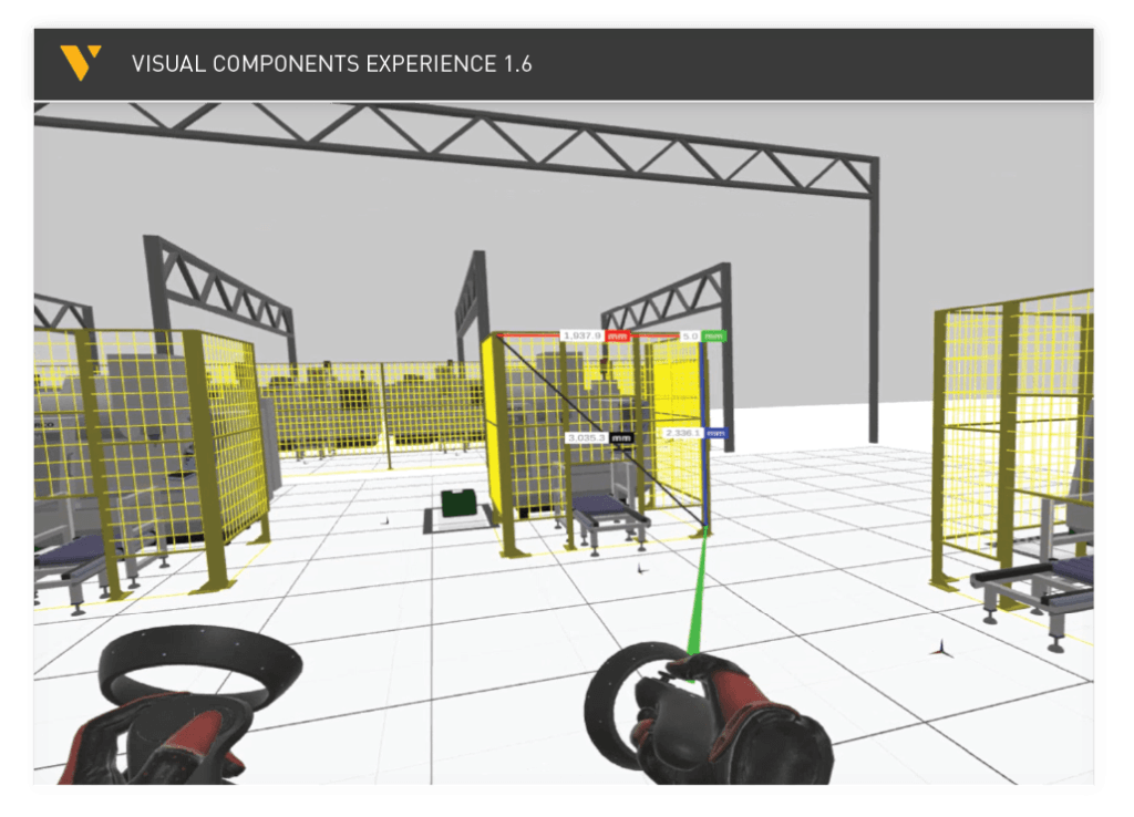
All new Visual Components Experience
Visual Components Experience becomes a more effective project communication tool with immersive UI, adaptive VR controls, and Point Clouds support. The default controls are easy to learn on the go and similar to most VR games. Point Cloud support to Experience helps you to create actual manufacturing scenes with simulations for improved collaboration on your projects. Check out the Release Notes to learn more about new additions.
Connection to Fanuc Robots
Visual Components now offers a native connection to Fanuc Robots, one of the most widely used robot brands in the world. With Visual Components 4.4, you can connect your simulations with Fanuc’s Virtual and Physical robot controllers through a communications medium like Fanuc PC Developer’s Kit or Robot Server Package.
With Fanuc Connectivity, you can benefit from Visual Components easy-to-use layout configuration and simulation tools and connect your simulations with Fanuc robot controller through Fanuc RoboGuide for visualizing digital twins and virtual commissioning use cases. You are now able to validate your programs with more accurate cycle times and robot paths. Remotely monitor the performance of your manufacturing systems with Fanuc robots and even use VR to collaborate and communicate your programs with your peers and customers.
We’ve also updated our Free-to-use Fanuc Post-Processor to support more programming statements and enable you to seamlessly transfer your programs to the physical or virtual Fanuc robot controllers. Click here to download the updated post-processor and read more about the improvements.
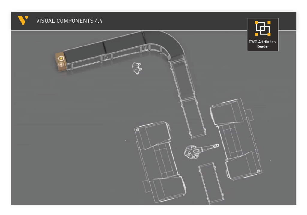
Convert your 2D Drawings to 3D Layouts Fast!
We’ve introduced a new feature, called CAD Attribute Reader, that reads your 2D CAD data and converts them into 3D layouts. Save your time spent on designing the layouts by making use of your available CAD data. The compatible 2D drawing formats are Autodesk DWG and DXFs. As the same states, the CAD attribute reader reads the attributes or properties of components in 2D drawings and generates a corresponding 3D model.
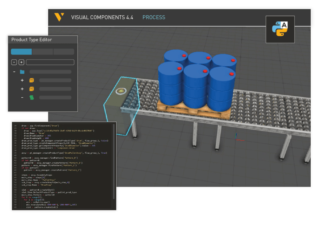
Process Modeling Improvements with APIs
Process Modeling Improvements include the addition of various Python APIs to simplify your tasks to avoid repeatability and manual work. Product Assembly Creator API, for example, allows you to import your scripts to create fully functional and simulation-ready 3D product assemblies within seconds. We’ve added some new components and will consistently add more in our eCatalog using APIs for practical warehousing use cases. Process Modeling Resources are smarter with new behaviors like dynamic object avoidance, collision scanning, and improved decision-making for speed adjustments.
Here is an example of a customer case from Sweden where they simulated an assembly of complete house structure utilizing our open APIs,
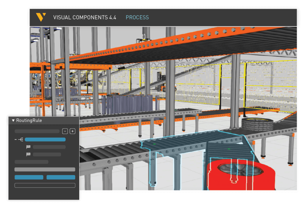
Product Routing Rule, Position Frame and More…
Routing rules
Assign the product routing rules for different product types in the updated panel. Products defined through process modeling are supported in the Routing Rule panel to help you assign and view product routes on conveyors according to your needs.
Product Position Frame
Process Statements now support the product positioning properties. Adjust your product location and orientation in simple steps while setting up your simulations. One use case where this feature can come quite handy is the simulation of an assembly line where a product needs to be adjusted, flipped, or turned for tasks like screw tightening, welding, painting, etc.
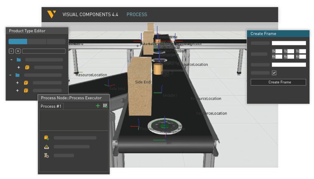
Many other improvements are made to Process Modeling to help you manage your tasks with simpler workflows.
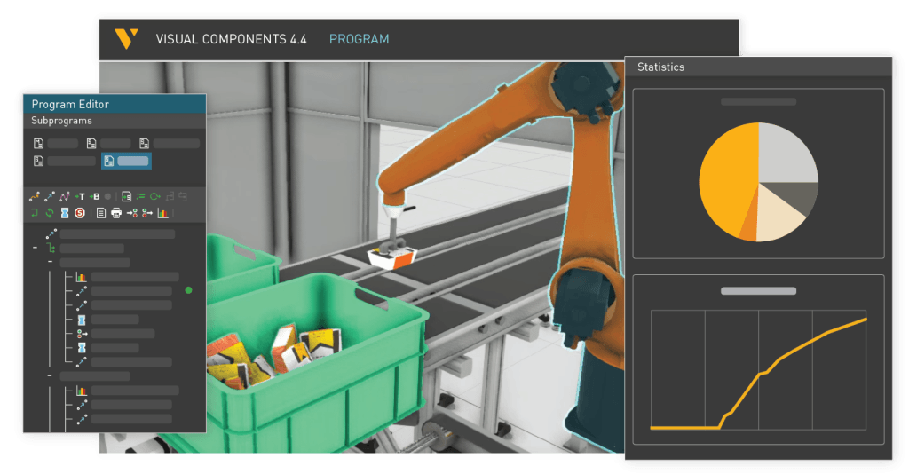
Updates to Robot Programming
Some new statements have been added to robot programming for more flexibility, better application of control flow logic, and improve your overall experience of programming robots. Some of these updates include Switch Statement for robot programming, ElseIf Statement with multiple branches, Statistics statement to measure robot state during simulation for better utility and simple cut/paste statements to help you quickly make any modifications.
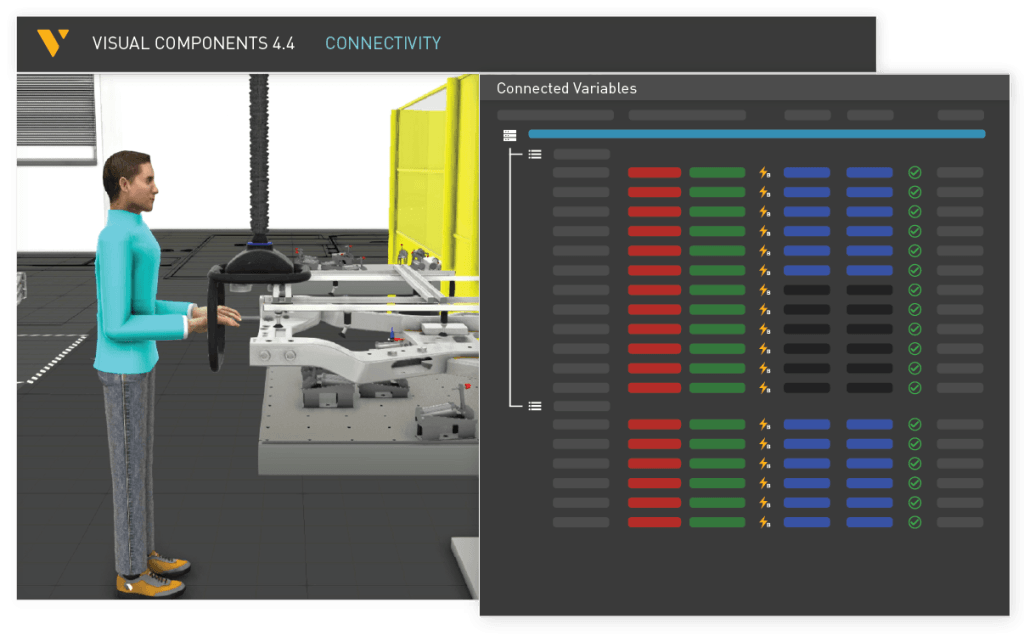
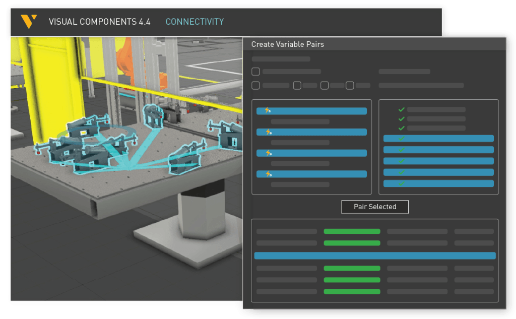
Connectivity UI Updates
We’ve made UI improvements to help you manage the connectivity of elements to help with virtual commissioning applications. Manage the connectivity of robots, sensors, PLCs, and other components with a more streamlined interface. The IO configuration is much easier now with improved UI for searching, pairing, and unpairing variables.
Check out the Release Notes to learn more about the features and maintenance updates in this release!
Further reading
Visual Components 5.0 – The fastest way from concept to reality
Visual Components 5.0 is here, and we’re excited to introduce this all-in-one manufacturing simulation platform now supercharged with major upgrades.
Introducing Visual Components 4.10 – Design beyond limits
Design beyond limits. That’s the promise of Visual Components 4.10. As manufacturing and robotics evolve, we continue to prioritize usability, ensuring that our tools not only keep up with industry...
Introducing Visual Components 4.9 – Craft with clarity
The latest version of our manufacturing simulation and robot offline programming solution is here, bringing improved clarity to production planning and optimization in manufacturing. With greater clarity, our users can...