Optimizing flexible manufacturing systems with Visual Components at MAG
In this case study, we’ll show you how MAG’s Factory Automation department used Visual Components to design and optimize a flexible manufacturing system for unmanned or reduced-manning production.
Optimizing flexible manufacturing systems with Visual Components at MAG
Automobile manufacturers are outsourcing ever larger parts of their production to suppliers. Due to the increasing variety of models, suppliers are faced with the challenge of processing even smaller batch sizes efficiently and economically. Many manufacturers are turning to flexible manufacturing cells, which can process rapidly changing orders autonomously and produce parts such as transmission housings and steering knuckles around the clock, largely without personnel. They are complemented by measuring, assembly, and cleaning applications that complete the mechanical machining process.
FFG Europe & Americas unites major players from the German, Italian, Swiss and American machine tool industry with a broad range of milling, turning, grinding, and gear manufacturing technology, designs individual automation concepts and integrates machines with peripheral equipment for assembly or measurement. In this case study, we’ll show you how MAG’s Factory Automation department used Visual Components to design and optimize a flexible manufacturing system for unmanned or reduced-manning production.
Utilizing the eCatalog and reusable components for fast and accurate layout design
MAG’s first step was to create a layout of the cell, which requires careful precision with flexible manufacturing systems. It was crucial that all systems interlock seamlessly and that the entire material flow, from the delivery of the pallets to their onward transport to the next production station, takes place without any delay. This was especially challenging since different workpieces have different processing times.
Using a combination of custom components and components included in the eCatalog, MAG was able to model the cell with relatively little effort. For robot models, MAG utilized the Visual Components eCatalog, which contains more than 1,400 robots, including their kinematics, axis limits, accelerations and positional accuracy. For designing their custom components, MAG found the geometric and kinematic properties of their machine tools could be easily reused from existing CAD data.
Marcel Deess, Project Manager Digital Factory / Automation at MAG, who was responsible for the project, reported, “The CAD models of the workpieces in almost all cases are provided as 3D models, in STEP or IGES format or as native data. With Visual Components, there are no problems with importing CAD models. We also have experience with other simulation tools, but these seem much more complicated to us; people often think they come from the 80s. The Visual Components software, on the other hand, is very logical to use.”
The CAD models of the workpieces in almost all cases are provided as 3D models, in STEP or IGES format or as native data. With Visual Components, there are no problems with importing CAD models.
Marcel Deess, Project Manager Digital Factory / Automation at MAG
Validating the layout and workflow with simulation
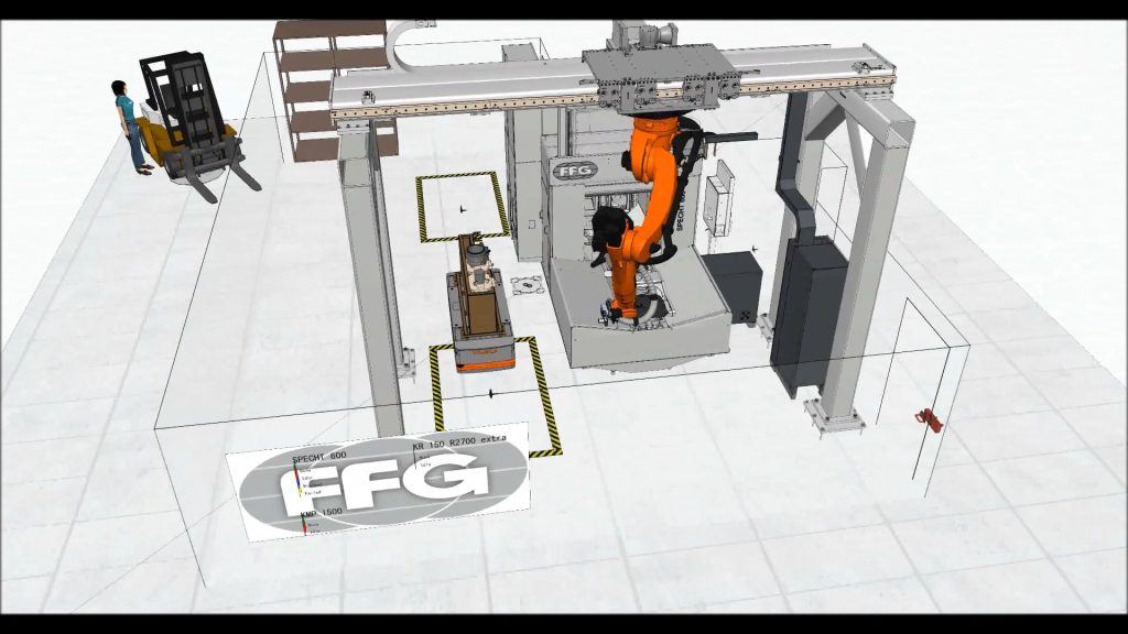
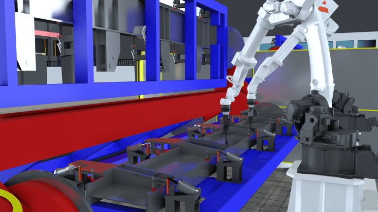
Once the simulation model was created, MAG was able to dimension the length, height and position of the portal supporting the robot exactly in such a way that the robot could move to all desired positions within a short time, taking into account its axis limits, without collisions between robot, pallet, and machine.
MAG designed and optimized the arrangement and dimensions of the manufacturing system as well as the offline programming of the robot. MAG used Visual Components to simulate the entire production process and the smooth cooperation between AGV, robot, and machine tool. Utilizing the simulation model, non-productive times were minimized and issues such as robot accessibility and collision avoidance could be clarified.
Once the simulation model was completed, MAG exported a virtual reality model of the cell, as well as 3D PDFs and videos showing the simulated production process from all possible angles. They also used Visual Components to generate statistics and tables, as well as 2D drawings documenting the arrangement of the machine, robot and portal. Data for controlling the robot could also be transferred directly from Visual Components.
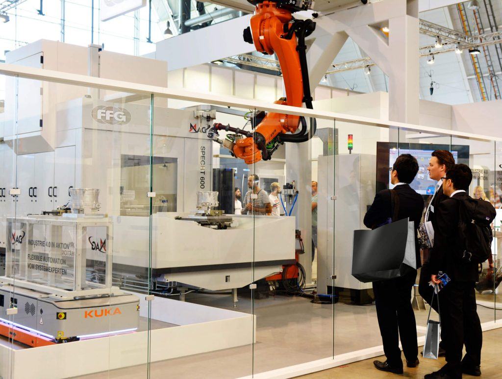
The completed cell
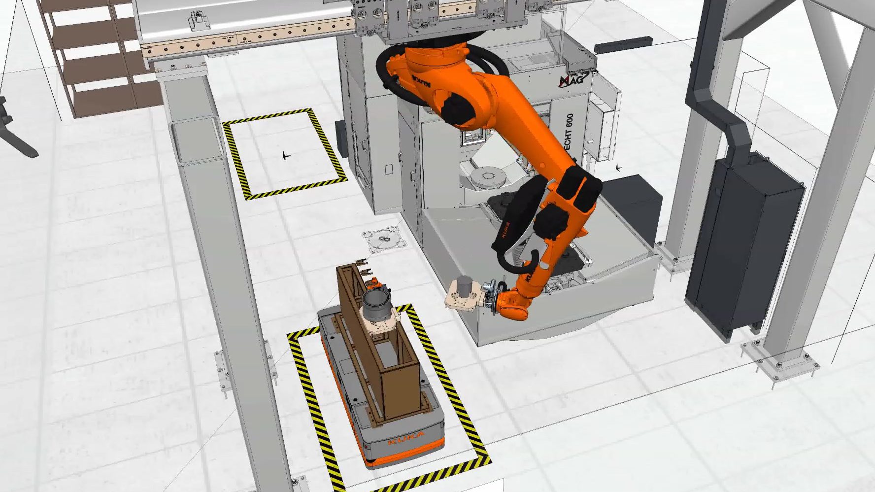
The cell MAG designed consisted of a SPECHT® 600 machining center and a KUKA Quantec robot equipped with a SIEMENS Vision MV 400 camera. There were also Autonomous Guided Vehicles (AGVs) transporting workpieces to and from the production system.
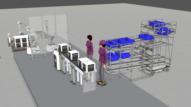
The workpieces are initially fed by intelligent, autonomous vehicles (KUKA KMP 1500), which supply the production system with the workpieces fixed on pallets in perfect timing and controlled by a manufacturing control system. These AGVs, which are controlled via WIFI, can move freely and without the need for conventional lane guidance or navigation elements. Using their laser scanners, the AGVs are able to avoid obstacles and achieve a positioning accuracy of just a few millimeters.
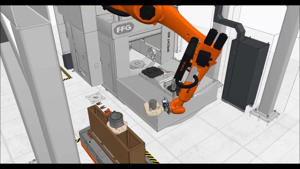
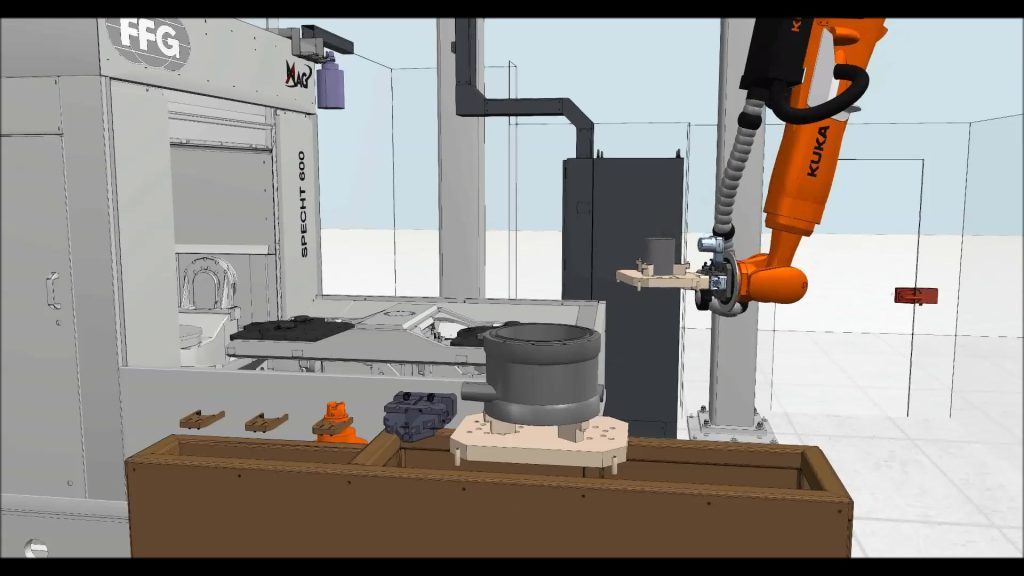
A KUKA Quantec robot with 6 axes is suspended overhead from a portal in front of the SPECHT® 600 machining center; a 7th axis, the linear axis along the portal, is also managed by the KR C4 controller. The robot is equipped with a SIEMENS Vision MV 400 camera, which enables the gripper of the robot to be positioned exactly with respect to the pallet with the workpiece. In this way, the robot can grip the workpiece pallets and feed them to the machining center with its pallet changer. The pallet changer then swivels 180° into the working area to load the machine tool.
In addition to loading and unloading the machine tool, the KUKA Quantec robot can perform tasks such as chip control, removal of chip pockets, and general cleaning tasks on the machined workpiece. The robot can also perform activities such as chamfering and deburring while the machine tool is already machining the next workpiece. And, with the camera attached to the robot arm, permanent quality control can be carried out with regard to the completeness of the holes drilled in the workpiece.
Winning more projects while saving time and money
When asked about the impact Visual Components had on this project, Marcel pointed out both the bottom line and selling benefits.
“In any case, because the simulation saved us a lot of time and money!” said Marcel.
“And, the simulation was not only very well received internally, e.g. by our sales department, but the customers are also enthusiastic when they can see “their” plant at an early planning stage. With Visual Components, they can for example change the position and parameters of a robot in order to optimize the system exactly according to their needs. This not only avoids costly planning errors, but also supports us in the quotation phase and helps us to sell more successfully.”
Because the project was so successful, it was also exhibited at the AMB 2018 trade show. In addition to the real manufacturing cell, the “digital twin” modeled with Visual Components, the simulation, and its results were presented on screens. Customers and trade show visitors liked the fact that process and system simulations ensure maximum transparency right from the planning phase.
With Visual Components, they can for example change the position and parameters of a robot in order to optimize the system exactly according to their needs. This not only avoids costly planning errors, but also supports us in the quotation phase and helps us to sell more successfully.
Marcel Deess, Project Manager Digital Factory / Automation at MAG
Using simulation to achieve flexible and intelligent production
MAG and Visual Components show how the production of the future can be closer to the customer, more flexible, and more intelligent. With Visual Components 3D manufacturing simulation software, the many parameters of a flexible manufacturing system can be adjusted for high total productivity, and decisive factors such as non-productive times, cycle times, layout topology, automation types, and machine up-time, can all be optimized.
About FFG Europe & Americas
FFG Europe & Americas unites major players from the German, Italian, Swiss and American machine tool industry with a broad range of milling, turning, grinding, and gear manufacturing technology, and the knowhow of the renowned machine tool brands VDF Boehringer, Hessapp, IMAS, Jobs, MAG, Meccanodora, Modul, Morara, Pfiffner, Rambaudi, Sachman, Sigma, SMS, Tacchella and Witzig & Frank.
At FFG, the activities of DIGITAL FACTORY and INDUSTRY 4.0 are combined in the new DIGITAL FRIENDS brand.
Further reading
BENTELER rolls out the production technology of tomorrow with the help of Visual Components
Together with BENTELER Automobiltechnik, Karlsruhe Institute of Technology uses modern factory planning software from Visual Components to develop innovative production technologies.
Virtual Manufacturing Project Case Study: Driving Sales with 3D Simulation
In this case study, we’ll review a project they recently completed to drive sales of their lean manufacturing products, using the Visual Components Experience app.