Introduction to Process Modeling
In this article, we’ll give you a short introduction to the concepts and functionality behind process modeling, a major new feature in Visual Components 4.2.
A major new feature we introduced in Visual Components 4.2 is Process Modeling; a fast, easy, and visual way to define and manage products, processes, and process flow in your layouts. This new feature provides many important benefits, such as simplifying layout creation and simulation setup, streamlining the modeling and simulation workflow, and improving simulation performance. To help you better understand the Process Modeling workflow, as well as the concepts and functionality behind Process Modeling in Visual Components, we’ve created this short introductory article.
Process Modeling concept with example
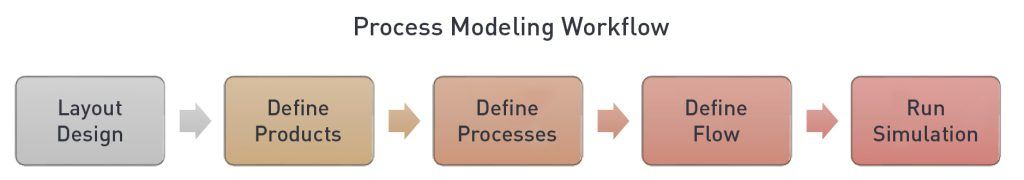
The Process Modeling workflow was designed to resemble how real-world production design is done in practice. It consists of the following 5 steps:
- Layout design.
- Define products, their visualization, structure and properties.
- Define processes, like machines, workstations, inventories and buffers using task statements.
- Define flow by creating sequences of processes that products must complete.
- Run simulation, collect KPIs, make necessary changes to achieve your goals.
Next, we’ll go through each step in more detail, using a small machining and painting cell as a reference example.
1. Layout Design
The first step in the workflow is to design or configure the physical layout of the production system. This can be created using simulation-ready components from the eCatalog and/or CAD data, which you can import directly into the software. Equipment should be placed in the correct position and orientation, and stations, walkways, buffers, fixtures, and spacing requirements should all be factored into the design.
For our reference cell, we’ve created a layout with 2 processes: machining and painting. We’re using a robot to load/unload parts in the lathe and a human to manually perform the painting at a workbench. We’ve also added some conveyors to help transport products between processes.
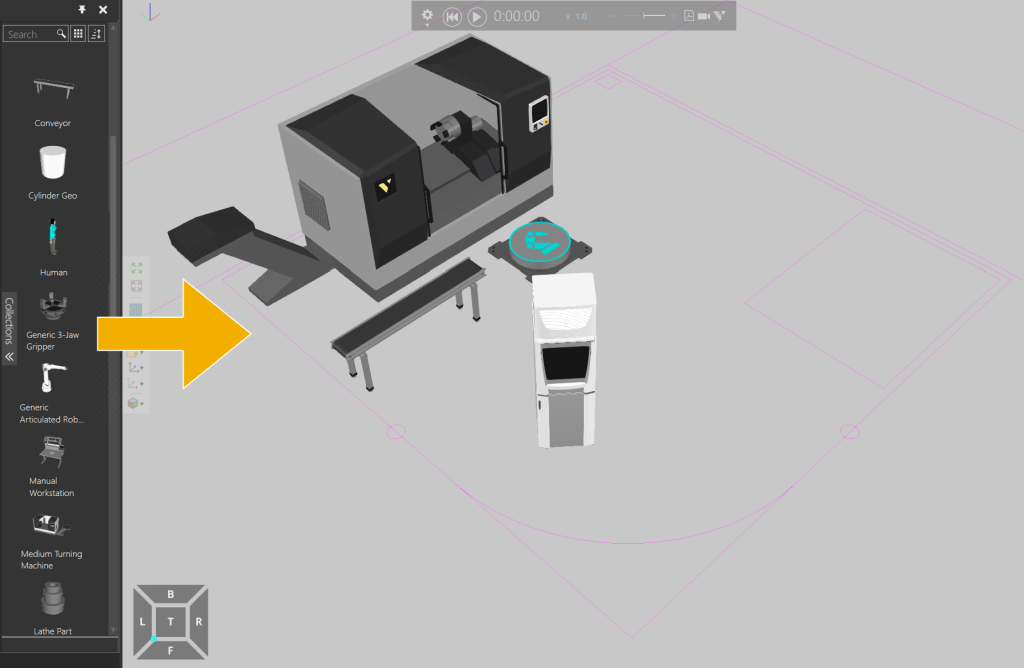
Layout creation using simulation ready components
2. Define Products
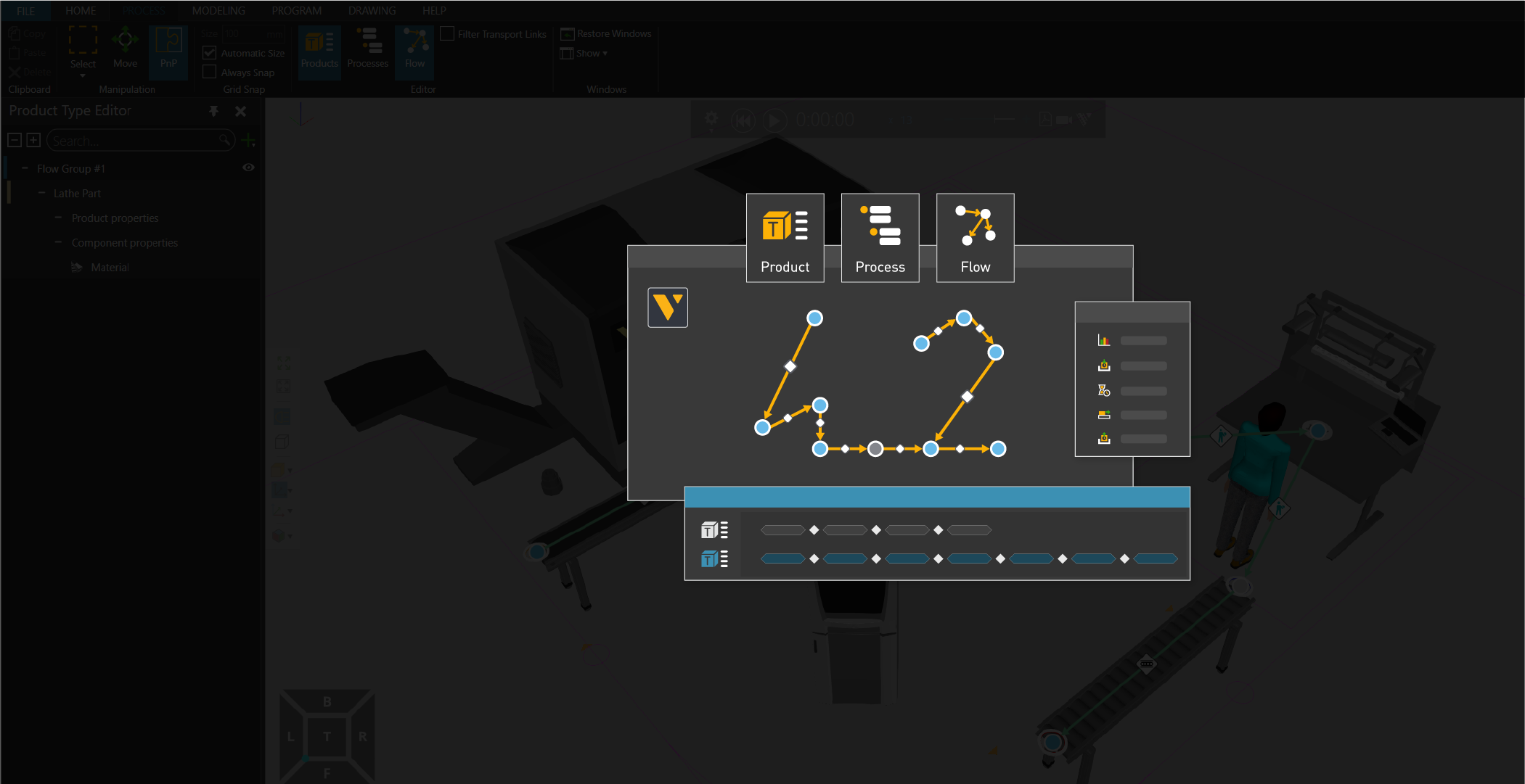
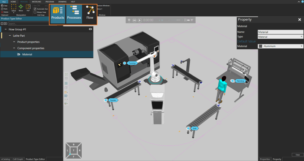
A Product is an entity that goes through a certain process in a layout. Products that undergo processes can be defined in this phase. From the Product Type Editor, you’re able to configure and manage the following:
- Product flow group; which is the collection of product types sharing the same production flow sequence. Let’s name the first flow group as Flow Group #1.
- Product type name; this can be a short description of the product like cylinder, car tire, motor plate, etc. In this case, the product is a ‘Lathe Part’ so let’s keep this name.
- Product properties; these can include parameters like dimensions, weight, material, etc. We want to specify that this lathe part is of ‘Aluminum’ material.
- 3D product geometry; a 3D geometry can be imported and selected as a product like in this example, where we have added ‘Lathe Part’ as an external CAD file.
Product Type Editor with view of product properties
3. Define Processes
A process is a representation of a machine, work phase, inventory, buffer or some other production step. In Process Modeling, a Process is expressed as a set of statements, which assign certain behaviors to a product. Processes are built from statements using the Process Editor. With routines and statements, machines can be configured to behave like their real-life counterparts, such as machine doors opening and closing, processing times, product geometries changing with processes, parts attachment, and so forth.
Before defining processes, it’s important to consider how products should evolve during production. In our reference cell, our products undergo two different processes.
- Process #1 is Turning, where the products are lathed in a machine.
- Process #2 is Painting, where the products are painted a gray color.
Now, we need to define the production steps for each process. For Process #1, we’ve specified the following steps:
- A robot picks the incoming product from the conveyor and transports it to the machine. We use a TransportIn statement to express this step, and it appears as the first step in the Process Executor.
- Next, we want to program a short delay so the robot arm can move out from the machine before the process starts. So, we add a short Delay
- Before the turning process begins, we need to make sure the machine doors are closed, so let’s use a MoveJoint statement to move the joints of the door to close.
- Now, the machine should start the turning process, so let’s add a Delay statement as ProcessTime.
- After the turning process is finished, we want the machine doors to open so the robot can retrieve the part, so let’s add another MoveJoint
- Once the doors are opened, we want the robot to transport the product out of the machine, so we need to add a TransportOut
The production steps for the painting process can be defined by following a similar workflow. Once processes are defined with process modeling, the production steps can be managed via the ProcessExecutor action panel, and adjustments can easily be made.
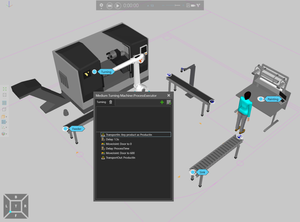
Process Editor showing the production steps in Process#1 – Turning
4. Define Flow
A flow is the sequence of processes that products follow in a production system. In process modeling, products are defined in groups based on the path they follow during the simulation. These groups are called flow groups. Using the Process Flow Editor, you’re able to define flow groups and the production flow for each product. You’re also able to define the transport links, which determine how products are transported between two processes during the simulation. A resource, such as a human, robot or AGV can be assigned to each transport link, which then transports products based on its capabilities.
In our reference cell, we have only one flow group (we previously named this ‘Flow Group #1’), as all our products are completing the exact same route. Before we define this flow group’s route in the Process Flow Editor, let’s plan the route we want it to take:
- First, we need a source to produce products into the system, so let’s import a Feeder from the eCatalog and add it to the beginning of the first conveyor.
- The first process we want our products to undergo is Turning. We’ll want our robot to pick products at the end of the first conveyor and place them into the machine for this process.
- Next, we want the robot to pick the products from the machine and place them onto the adjacent conveyor, which transports them to the Painting
- Once products reach the end of the conveyor, we want our human resource to retrieve them and transport them to the workbench for Painting.
- After the products are painted, we want the human to transport them to the exit conveyor.
- We also want these finished products to exit the simulation at the end of this conveyor, so we need to add a ‘Sink’ process here.
Once the route is planned, the flows can be defined easily in the Process Flow Editor, using your mouse to create links by selecting/clicking processes and resources in the 3D world.
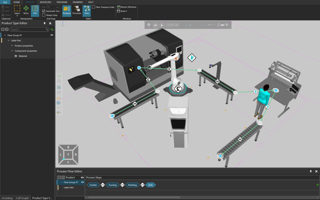
Process Flow Editor with visual representation of the production sequence and process steps
5. Run Simulation
When your model is set up, it’s ready for simulation. Basic multimedia controls can be used to play the simulations, collect KPIs, make modifications, and export in a variety of formats.
In this article, we gave you a short introduction to the concepts and functionality behind process modeling, a major new feature in Visual Components 4.2. Process modeling introduces a simple yet powerful way to manage processes and production flow in your layout. It also provides an improved user experience by simplifying layout creation and simulation setup, streamlining the modeling and simulation workflow, and improving simulation performance.
If you’re interested in learning more about process modeling or other new features in Visual Components 4.2, get in touch with us to schedule a free, personalized web demonstration!
Further reading
Visual Components 5.0 – The fastest way from concept to reality
Visual Components 5.0 is here, and we’re excited to introduce this all-in-one manufacturing simulation platform now supercharged with major upgrades.
Introducing Visual Components 4.10 – Design beyond limits
Design beyond limits. That’s the promise of Visual Components 4.10. As manufacturing and robotics evolve, we continue to prioritize usability, ensuring that our tools not only keep up with industry...
Introducing Visual Components 4.9 – Craft with clarity
The latest version of our manufacturing simulation and robot offline programming solution is here, bringing improved clarity to production planning and optimization in manufacturing. With greater clarity, our users can...