Solutions
Factory layout design
Remove the guesswork from designing or optimizing your factory layouts.

Easy to use
We offer an intuitive interface that simplifies factory layout design. Quickly design, optimize and adjust layouts with minimal training.

Minimize risks
Our accurate simulation capabilities help users identify and mitigate risks in the layout, ensuring a safer and more efficient manufacturing environment.

Test ideas
Visual Components lets you quickly test various layout scenarios, providing the flexibility to experiment with different designs and find the most effective solution for any manufacturing challenge.
Maximizing efficiency in factory design
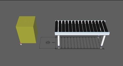
Factory layout design is essential for optimizing manufacturing processes, involving careful selection and placement of equipment to achieve specific goals. It comes in two forms: greenfield, where new facilities are designed from the ground up, and brownfield, where existing layouts are revised to improve efficiency within existing constraints. This strategic approach ensures that every aspect of the factory layout, from material movement to equipment relationships, aligns with the organization’s objectives and maximizes operational efficiency.
Defining and launching a project
Launching a factory layout project involves setting formal goals, defining scope, and identifying constraints and stakeholders, especially challenging in brownfield scenarios with limited space and ongoing production. The process begins with broad concepts to engage multiple stakeholders, progressing through iterative development, presentation, and revision of layout options.
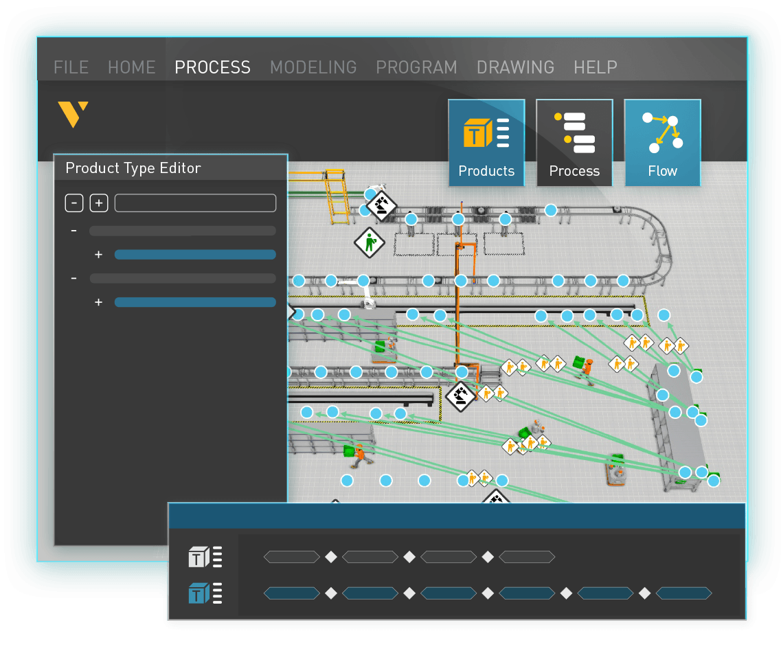
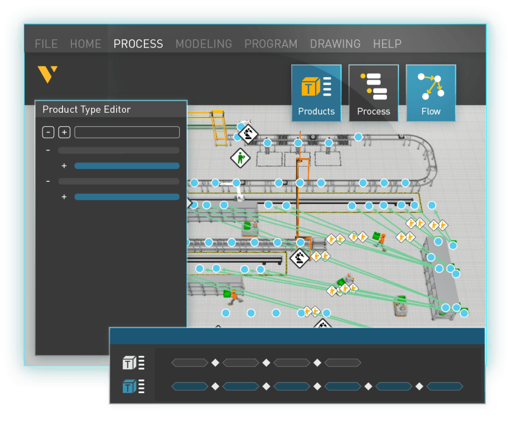
A key challenge is conveying the practical functionality of the proposed layout, where tools like Visual Components’ graphical discrete event simulation prove invaluable in demonstrating the layout’s effectiveness in various scenarios. This structured approach ensures thorough planning and stakeholder alignment for successful project execution.
Factory layout design with Visual Components
Factory layout design is a detailed, iterative process, requiring refinement as new data on equipment and operations emerge.
Tools like Visual Components expedite this optimization, emphasizing accuracy in modeling based on operation times, dimensions, and more. Validation is achieved by matching simulated outcomes with actual production results. This approach goes beyond basic CAD, using real-time simulation to ensure a functional, efficient, and adaptable factory environment.
Plant layout design process
How do you get started with plant layout design? Here, we provide a step-by-step example using Visual Components to help you get started.

For manufacturing engineers
Quickly design, optimize and adjust layouts with minimal training to test what-if scenarios and minimize risks.

For production managers
Accurately optimize process and mitigate risks to maximize efficiency according to your operational needs.
For system integrators
Improve planning, decision-making and sales processes to boost productivity, reduce errors, enhance collaboration and customer engagement.
How are our customers using Visual Components for factory layout design?
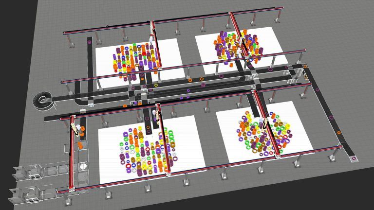
How Güdel optimized tire logistics with automated sorting and palletizing using Visual Components
In this case study, we’ll show you how Güdel, one of the world's leading providers of automation, linear, and drive technology; used Visual Components to plan and design an automated…
How ECOSPHERE helped JenaBatteries automate redox flow battery production with Visual Components
If more green energy is to be generated from the sun and wind, electricity needs to be stored for dark and windless times. To meet this challenge, innovative solutions are…
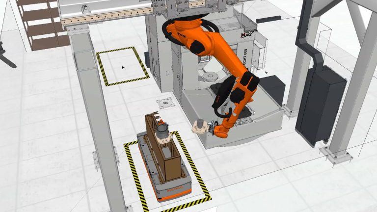
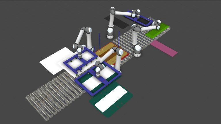
Optimizing flexible manufacturing systems with Visual Components at MAG
In this case study, we’ll show you how MAG’s Factory Automation department used Visual Components to design and optimize a flexible manufacturing system for unmanned or reduced-manning production.
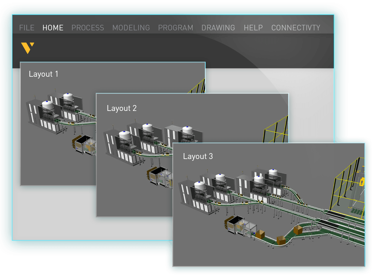
Master factory layout design in Visual Components
Introduction to layout configuration
Learn the basic layout set-up including Visual Components user interface, feature and basic tasks.
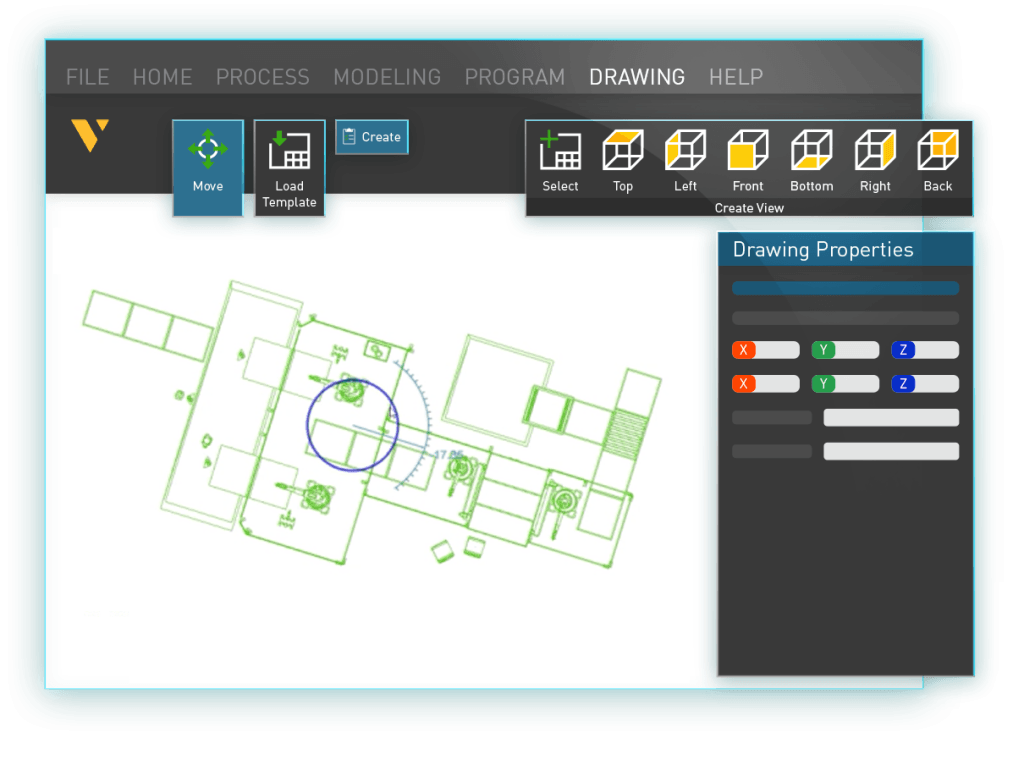
Import and export floorplans
Learn how to import and export 2D floorplans for building layouts in the 3D world.
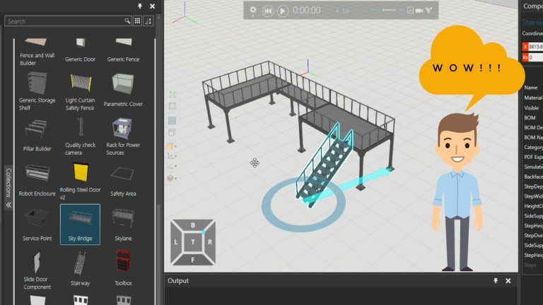
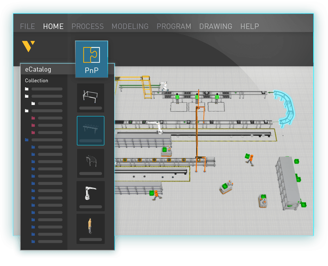
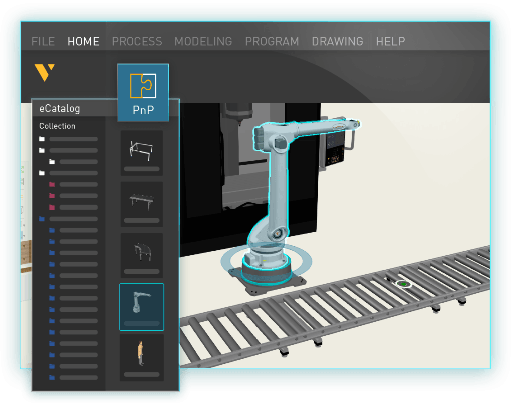
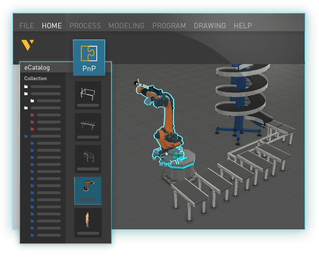
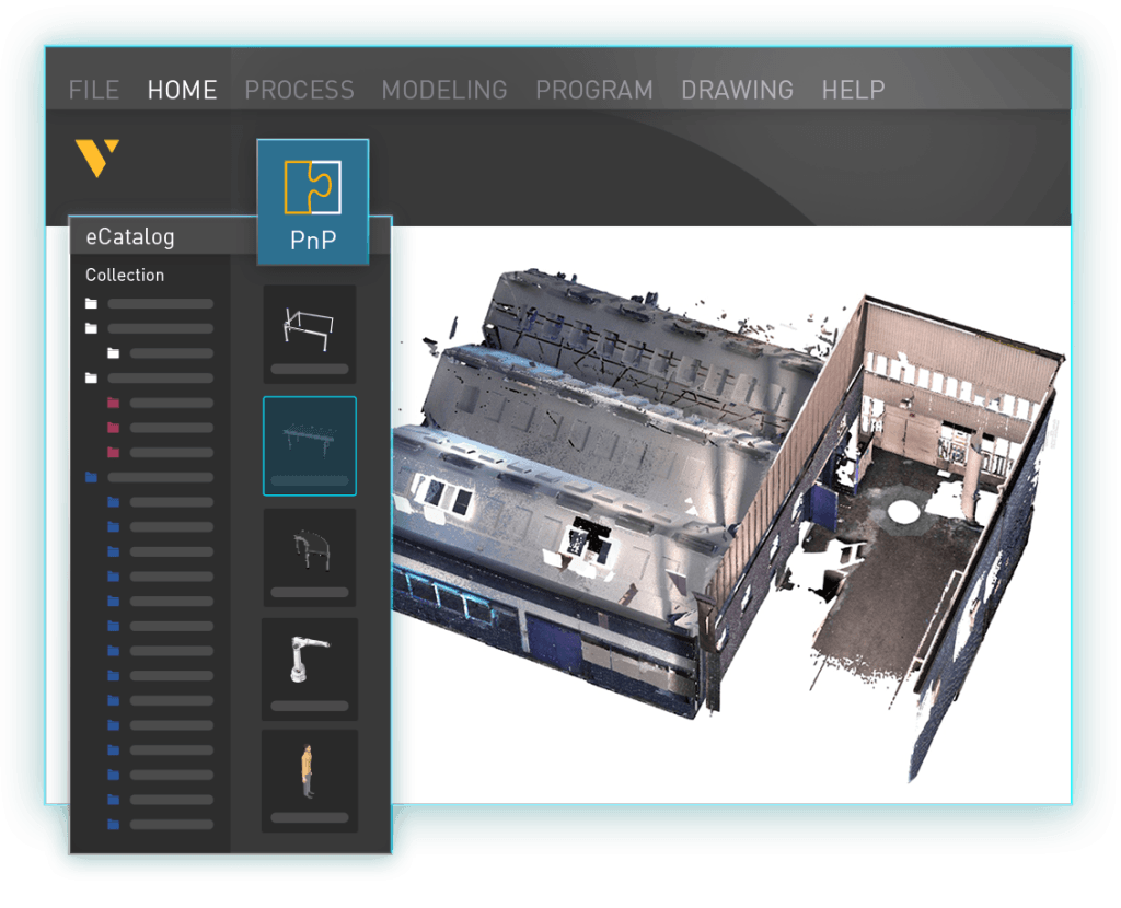
eCatalog factory facilities – an overview
Learn how to locate collections in eCatalog panels related to factory facilities.