Michelin streamlines manufacturing planning with Visual Components 3D simulation
When different teams see different things, it’s hard to move forward. That was the challenge at Michelin’s plant in Thailand, where engineering drawings and CAD sketches couldn’t always get production, maintenance, safety, and quality on the same page. As projects became more complex and cross-functional, so did the need for a shared visual understanding. That’s where 3D simulation came in.
Moving beyond 2D for manufacturing planning
Clément Dupuis, a mechanical engineer at Michelin Thailand, was among the first at the company to explore Visual Components as a planning tool. Faced with the limitations of traditional methods, he needed a better way to visualize ideas and communicate them to others.
“If you’re not a mechanical engineer or don’t have a technical background, you’ll only see lines on paper. It can be a nightmare.”
Relying on 2D facility layouts and static presentations often meant that non-engineers saw “just lines on paper.” Important details (like how machines interact in space or how people move around them) were not obvious, making it hard for stakeholders to grasp the plan fully. This sometimes led to skepticism or a lack of buy-in for new ideas.
With Visual Components, Clement could quickly build digital layouts of factory areas using 3D scans of existing environments. The drag-and-drop interface allowed him to add machines, conveyors, and robots from the Visual Components eCatalog directly into the 3D world. This made it easy to iterate, compare options, and explore new ideas before committing to physical changes.
Fast and visual feasibility studies
At the very beginning of a project, before heavy investments, Clement would model the proposed changes to answer critical questions: Will the new equipment fit in our current space? Where is the optimal location for it? How will it interact with existing operations? Exploring these questions in 3D helped validate ideas (or flag issues) long before reaching the shop floor.
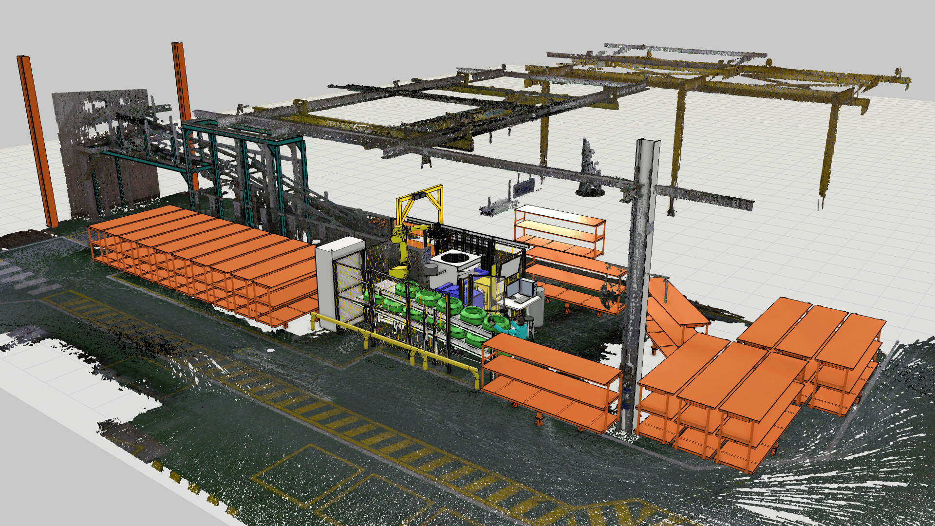
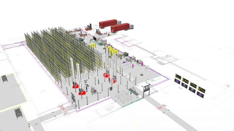
For example, when tasked with adding a new automated tire-handling machine in an existing production hall, Clement first scanned the hall to capture all current machines and structures into a point cloud. He then imported the point cloud into Visual Components (seen in the image at the top of the article) and placed the new machine, its feeding conveyor, and a robotic arm on top of the point cloud. This spatial simulation immediately showed how the new setup would look and fit. The team could see, for instance, whether there was enough clearance between the new machine and an existing one, or how the addition might block any aisles or access ways.
Because the model was easy to edit, multiple layout options were tested in a short time. In one scenario, the conveyor bringing tires to the new machine was initially placed on the left side; the simulation revealed that this position conflicted with a planned hoist pillar. Clement easily “mirrored” the conveyor to the right side of the machine with a few clicks, instantly generating a new layout option. This kind of quick iteration (moving equipment around to see the impact) allowed the team to compare alternatives and optimize the spatial arrangement without any physical trial and error.
The 3D feasibility models also served as an early warning system for spatial conflicts. In one case, two separate project teams discovered through the simulation that they had overlapping design ideas for the same space: one team’s conveyor path would have obstructed another team’s planned maintenance zone.
“I needed space. So, I would place something here (in the layout), and then the other team would come and say no because they had already planned to install something there. That’s why we then needed to rework our layout a bit.”
Seeing this conflict in the virtual model prompted a discussion and a revised design that accommodated both needs. Catching such issues in the planning phase averted what could have been a costly on-site clash or redesign later.
Designing for the people on the factory floor
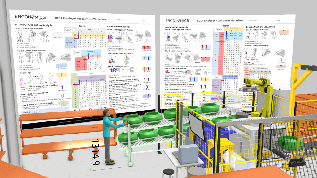
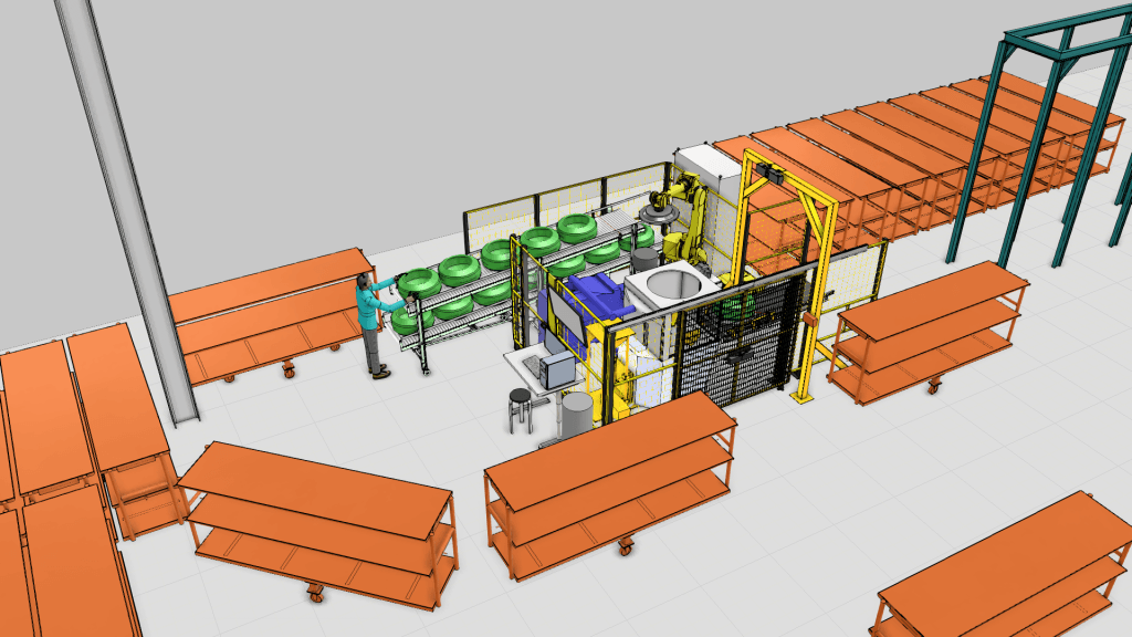
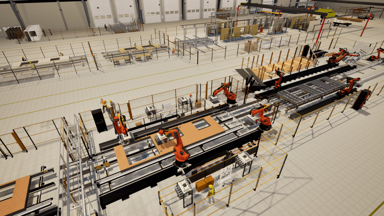
Beyond just fitting machines into the building, Michelin uses the simulations to consider the people who work with and around those machines. Clement’s models often include human figures or reference measurements to check ergonomics (like with the REBA Employee Assessment Worksheet component by ErgoPlus, seen in the image above). For instance, the team verified that an average-height operator could comfortably reach the new conveyor and machine controls at the proposed installation height. They also looked at operator workflow: how far would a person need to walk to perform routine tasks in the new layout? By comparing different arrangements in the model, they chose a layout that minimized unnecessary walking and twisting, aiming to reduce operator fatigue and improve efficiency.
“You can discuss with the ergonomic people and show them, ‘OK, we plan to put the conveyor at this height, so you will be able to reach it…’”
Simulations were also used to validate maintenance access. In one case, the team virtually demonstrated how a robot could be removed from a cell using a forklift, with safety fencing and clearance all accounted for. This gave confidence to the maintenance team and eliminated guesswork in the design.
Getting everyone on the same page
The biggest benefit, according to Clement, was the ability to bring people together around a shared understanding. Instead of static drawings, he would use the 3D simulation model live in meetings, orbiting around the layout, zooming into details, and even editing the design based on feedback.
“It’s not just like what you have in mind or a sketch on paper. You can show them something more accurate. Everyone can speak the same language.”
This helped break down silos between departments. Stakeholders from production, maintenance, safety, ergonomics, and leadership could all see the same thing and give feedback on the spot.
Because the software is intuitive, Clement could make changes quickly, even during a meeting. This allowed for active discussion and co-creation, rather than top-down presentations. Visual Components, in short, helped refine a plan collaboratively and in real-time.
Other Michelin engineers also highlighted how the ability to animate concepts directly from imported CAD models added another layer of clarity. Yannick Petitbout, Process Engineering Expert, explained that this made it easier to bring proposed ideas to life and communicate them in a way that everyone could immediately understand.
Supporting stories from other regions
As the benefits of 3D simulation became clear, Michelin’s management introduced Visual Components to other teams and regions, where engineers began applying it to their use cases.
Oranee Maneewongwicit, who works on automation projects in Michelin’s Thailand operations, found that simulation helped everyone reach a shared understanding. Her team was considering adding a robot to handle a task previously done manually. Communicating this idea to non-specialists became much easier with a dynamic model.
“When we present the solution, it’s not easy to make everyone understand, but when we have [a] dynamic presentation it’s… easy to make a decision – OK, we should go or we should not go and do this.”
During that same project, the simulation revealed a critical issue:
“I just found something abnormal after the robot handled some product – the gripper [collided with] the machine,” Oranee said. Thanks to the 3D model, the team adjusted the design before implementation, avoiding a costly mistake.
Caining Xin, an automation engineer at Michelin’s plant in China, recently used Visual Components to model a workflow in a new workshop. Despite being new to the software, she found it intuitive.
“For me, it was easy to get started.”
She was able to simulate an automated guided vehicle transporting products through multiple process stages, learning the software as she went, helped by the Visual Components Academy.
A clearer path from concept to reality
Michelin Thailand’s experience with Visual Components shows how 3D simulation can turn abstract ideas into shared, visual plans that everyone can understand.
By enabling quick iterations and real-time feedback, Visual Components reduces miscommunication, builds confidence, and helps ensure that changes are well thought through before they reach the factory floor. For Michelin, Visual Components has helped make better decisions, faster, with everyone on board.
About Visual Components
Founded by a team of simulation experts and amassing over 25 years in business, Visual Components is one of the pioneers of the 3D manufacturing simulation industry. The organization is a trusted technology partner to a number of leading brands, offering machine builders, system integrators, and manufacturers a simple, quick, and cost-effective solution to design and simulate production processes and offline robot programming (OLP) technology for fast, accurate, and error-free programming of industrial robots.
Contact us today to explore how our solutions can help your business.
Further reading
MSK Finland advances robot cell automation and intralogistics planning with Visual Components offline programming and manufacturing simulation
MSK Finland increases efficiency in both robot cell automation and intralogistics planning using Visual Components robot offline programming (OLP) and manufacturing simulation software. By creating and validating robot programs virtually,...
Vaisala optimized and validated its new logistics center with Visual Components
Vaisala recently built a new logistics center at its Vantaa headquarters to support growing production needs. Using Visual Components’ 3D simulation platform, the automation team modeled the entire facility to...
Wiksfors uses Visual Components to bring renovation into the factory era with RenoChain
Modernizing Sweden’s aging housing stock calls for a smarter approach. With Visual Components, Wiksfors developed RenoChain, a factory-based renovation concept that uses simulation to plan and prove a faster, more...