KOCH Steuerungstechnik sets new standards in modular plant engineering with Visual Components
KOCH Steuerungstechnik uses simulation as the backbone of their workflow, driving every project from start to finish. In their work with HANSWEBER to automate a brushing station, KOCH used Visual Components right from the quoting phase. They modeled layouts, tested robot programs, validated system logic, and ran design reviews in virtual reality. Read on to see how simulation guided the project from concept to reality.
KOCH Steuerungstechnik develops smart robot solutions for mechanical engineering. Founded in 2021 and based in Germany’s Black Forest, the company has used Visual Components for digital factory planning from the very beginning. Not as a bonus, but as a core part of how they work. Whether it’s quoting, programming, or getting final approval, they develop digital twins using Visual Components that are involved in every step of the process of a project, from early ideas to commissioning.
A recent project to automate a brushing station for Hans Weber Maschinenfabrik GmbH (HANSWEBER) shows how KOCH puts this approach into practice and the benefits that come with it.
Rethinking processes: From scaled gearwheels to stacked workpieces
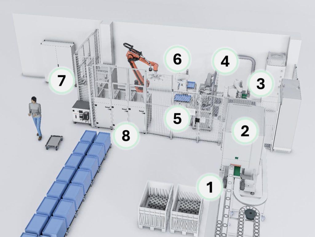
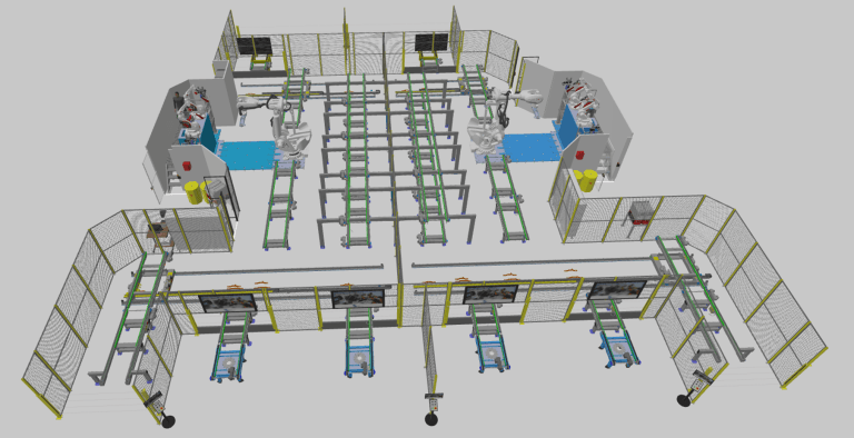
One of KOCH Steuerungstechnik’s customers, a gear and transmission manufacturer, uses a HANSWEBER machine to brush and descale gears after heat treatment. Once the gears come out of the hardening furnace, they are scaled and covered with dirt. They’re manually unloaded from the hardening box, as shown in Figure 1, and placed into the brushing station (1). After brushing (2), the workpieces are aligned in the correct position (3), then laser-marked with an individual ID (4) and stacked in baskets on two tables (5)(6).
KOCH’s job was to automate the unloading process. The cleaned and marked gears needed to be placed into trays inside wire baskets for the next stage of processing (7)(8).
The particular challenge: a new part exits the brushing station every two to three seconds. With limited space to work in, KOCH had to design a highly efficient process with an optimized cycle time.
Simulation starting on day one: how the digital twin is created
KOCH begins building the digital twin as early as the quotation phase. Georg Schepers, the commercial director for technical sales, creates an initial layout using KOCH’s own Visual Components library. Even without a technical background, he’s able to put together a working model that closely reflects the final robot cell. This is made possible by a systematically structured pool of modular subsystems with defined interfaces.
But it’s not just about robot movements. KOCH evaluates the entire material flow, from the previous process (hardening) to further processing after brushing. The machine operators are therefore also represented in the simulation: When do they have to fetch material? How often do they move empty baskets through the hall? Which routes of the machine operators cause bottlenecks?
With the digital twin, KOCH can quickly and easily simulate a wide range of scenarios. In this case, the simulation revealed that fewer trays actually improved efficiency. Less transport meant smoother flow. These kinds of insights can be brought into the quotation phase, giving the customer a clearer picture of what the solution will deliver right from the start.
Virtual and physical product validation in mechanical engineering – the Institute for Product and Service Engineering of the Hochschule Furtwangen and KOCH break new ground
The modeling of the digital twin follows the X-in-the-loop principle. When developing modern automation solutions, an engineer must be able to test individual subsystems in a near-system environment in the early phase of product development, even if the overall system is still incomplete.
Today’s automation setups combine mechanical, electrical, and software elements, so an integrated development process is essential. Validation, not just verification, must be done from the outset and continuously throughout the development process. The basic idea is that continuous validation ensures a constant comparison between the objectives of the product and the respective development status achieved. Validation thus controls the entire product development process, contributes significantly to knowledge gain, and constantly stimulates new creative solutions.
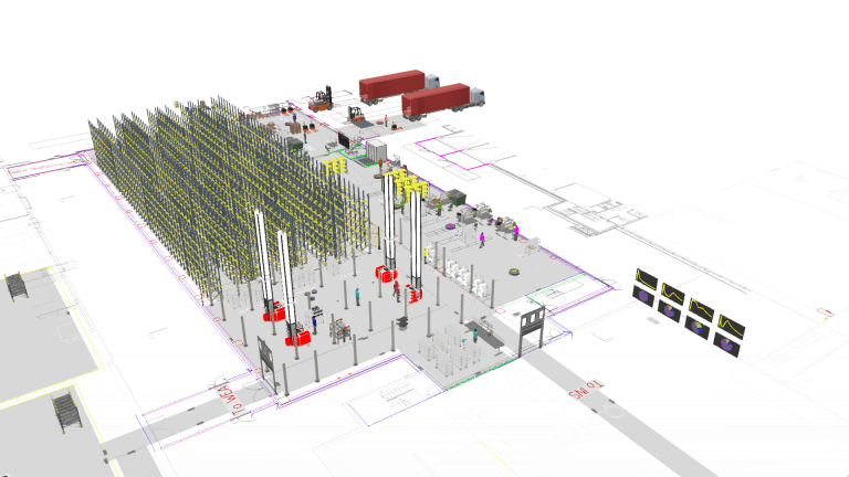
An example of using the X-in-the-loop approach for validating a subsystem, the robot cell for unloading the brushing machine, is shown in the following figure by two superimposed layers a) and b). The layers show the virtual and physical characteristics of the system in development (SiD) and the connected system.
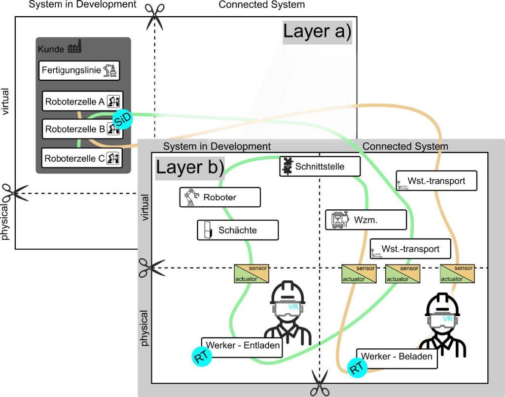
Layer a) shows the customer’s production line, which already includes two robot cells (A) and (C), as shown in Figure 2. The new brushing cell (B) is placed between them. As the figure shows, an overall validation is carried out. In the simulation, not only is the robot cell considered, but also the workpiece transport over the entire production line from the previous robot cell (A) to the subsequent robot cell (B), including the brushing machine and its coupled subsystems.
In layer b), the robot cell of the brushing machine is analyzed in detail. The workpiece transport to the brushing machine (1) and loading is part of the virtual and physical residual system, which is mapped in the simulation using process modeling in Visual Components and virtual reality. Sensors and actuators in the simulation can be used to physically interact with the brushing machine and load the workpieces into the brushing machine.
The transport of workpieces in the brushing machine (2), the position check (3), the labelling (4), and the stacking of the workpieces in empty baskets (5)(6) are also mapped using process modelling. The interface logic between the brushing machine tool and the robot is verified. The robot that picks empty wire baskets (7) and stacks the finished parts into the baskets (8) is the SiD (System in Development) in the virtual domain. The complete model simulates the interface to the brushing machine and all the necessary sensors and actuators linked to the robot. This allows, for example, the robot program to dip its basket gripper into the shaft until a light barrier detects a basket. The KUKA.Sim AddOn in Visual Components is used to configure and program the robot.
A machine operator who loads the robot cell with empty baskets (7) and unloads the baskets with the brushed parts (8) interacts with sensors and actuators via virtual reality with the robot cell, for example via a human-machine interface (HMI). The transport of workpieces to the next robot cell (C) is again part of the virtual residual system and is mapped using process modelling in Visual Components.
With this X-in-the-loop setup, KOCH can validate the brushing robot cell and its integration into the full system, long before everything is physically in place. It’s a practical way to test complex systems early and make sure everything fits and works as intended.
From virtual model to real robot movements
The digital twin keeps evolving as the project moves forward. New workpieces, alternative scenarios, and process improvements are added along the way until the model reflects a stable, reliable setup.
Robot programs are finalized within Visual Components, motion sequences are defined, and interfaces are verified. In more complex projects, such as a 3-tray loading system, the simulation is linked to BECKHOFF TwinCAT to test numerical control (NC) axes together with sensors and actuators under realistic conditions. The NC provides target positions, which are transferred to the simulation and checked. The HMI is also part of the simulation: the user interface is displayed and tested in the digital model via a web browser. This provides a holistic view of the robot cell long before the first real component is manufactured.
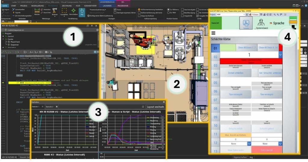
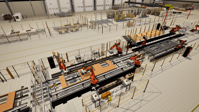
Figure 3 shows the Visual Components simulation environment. The window for the KUKA.Sim add-on (1) is located on the left-hand side; with KUKA.Sim robots can be configured and programmed in KUKA Robot Language (KRL). The overall layout of the brushing machine with the robot cell is shown in the center (2). At the bottom center is the window for analyzing the individual robots, the brushing machine, and the machine operators (3). The charts show how the individual subsystems are being utilized, what effects break times have, or how a malfunction can affect the entire material flow. On the right-hand side, you can interact with the simulation via BECKHOFF TE2000 (4) to validate user-friendliness, for example.
Approval in the virtual world – with all stakeholders
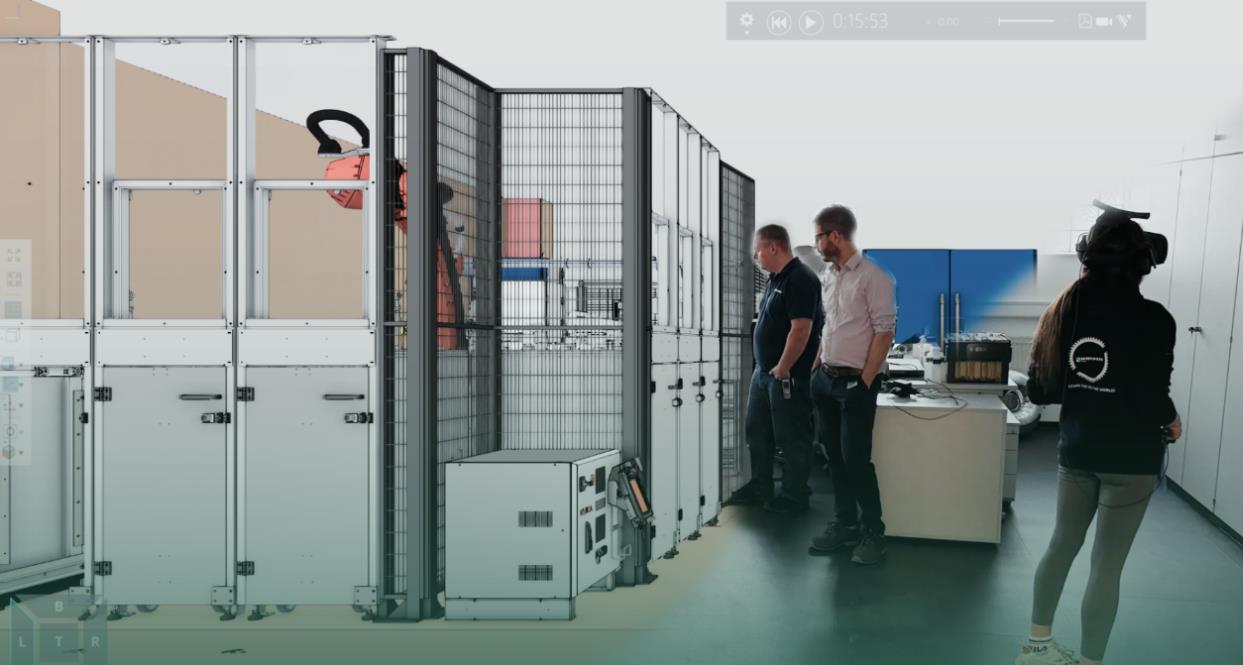
A key element of KOCH’s project methodology is interactive design approval using virtual reality (VR). Instead of looking at two-dimensional drawings, the customers are immersed in a walk-in VR world. There, they can check walking routes, verify sight lines, or, for example, validate safety distances.
Everyone gets involved: management, maintenance teams, project leads, and even future machine operators. Each stakeholder experiences the setup from their own perspective and can give feedback on things like cable tray placement, escape routes, or ergonomic issues. That input goes straight into the model, helping shape a solution that not only works on paper but also works in practice, for everyone.

Commissioning at the touch of a button
Once the actual plant is set up, the robot programs developed in Visual Components are transferred to the robot controller. Christian Koch, owner and responsible for all technical issues, imports the robot programs directly. Thanks to the realistic simulation, commissioning is quick and smooth. What used to take days of on-site programming now often takes just a few hours. Customers benefit not only from the speed, but also from the certainty that the plant will perform exactly as defined in advance. Unexpected problems? None whatsoever.
More than just a tool: simulation is a key principle
For KOCH Steuerungstechnik, simulation is a key part of the engineering process. The company doesn’t know the ‘old normal’ – plant engineering without digital twins. They’ve been using Visual Components since they started, and it’s become a must-have tool. Digital twins are the ‘new normal’ at KOCH – not because they’re trying to be innovative, but because they believe in them and know they work.
I wonder how people don’t use digital twins – and then wonder why their projects aren’t profitable. We’ve never done it any other way. And I can’t imagine how you could do it without simulation – the risk is immense!
Georg Schepers, Commercial Director, KOCH
The future is included: remote access from the digital twin to customer systems
KOCH is already planning the next step: integrating real-time data into the digital twin. The aim is to remotely check the status of robots, NC axes, sensors, and actuators during service calls. Real-time data synchronization between the customers’ systems and the digital twin via remote access could make support requests more efficient and increase the uptime of production facilities in the long term.
Simulation is a competitive advantage
The above project, which ran for six months, was not a special case. On the contrary, it is typical of the standard process at KOCH. What sounds like a secret recipe is based on two clear principles: modular system design and consistent simulation. Together, they allow KOCH Steuerungstechnik to design production systems that are technically superior, cost-effective, and inspiring for its customers. Visual Components is a central component of the company’s DNA.
About Visual Components
Founded by a team of simulation experts and amassing over 25 years in business, Visual Components is one of the pioneers of the 3D manufacturing simulation industry. The organization is a trusted technology partner to a number of leading brands, offering machine builders, system integrators, and manufacturers a simple, quick, and cost-effective solution to design and simulate production processes and offline robot programming (OLP) technology for fast, accurate, and error-free programming of industrial robots.
Contact us today to explore how our solutions can help your business.
Further reading
MSK Finland advances robot cell automation and intralogistics planning with Visual Components offline programming and manufacturing simulation
MSK Finland increases efficiency in both robot cell automation and intralogistics planning using Visual Components robot offline programming (OLP) and manufacturing simulation software. By creating and validating robot programs virtually,...
Vaisala optimized and validated its new logistics center with Visual Components
Vaisala recently built a new logistics center at its Vantaa headquarters to support growing production needs. Using Visual Components’ 3D simulation platform, the automation team modeled the entire facility to...
Wiksfors uses Visual Components to bring renovation into the factory era with RenoChain
Modernizing Sweden’s aging housing stock calls for a smarter approach. With Visual Components, Wiksfors developed RenoChain, a factory-based renovation concept that uses simulation to plan and prove a faster, more...