Next-level robot offline programming automation with model-based engineering
Explore how model-based engineering enables the next level of robot offline programming automation by connecting design and manufacturing through model-based definition. With validated manufacturing data exported via Capvidia tools to support weld import, Visual Components OLP software further automates and streamlines the entire robot programming workflow—resulting in faster programming and fewer errors.
The rise of automated robot programming
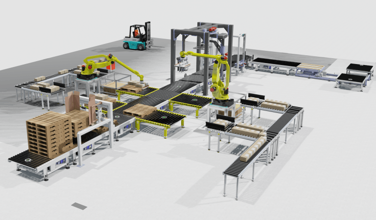
Manufacturers are under increasing pressure to produce faster, with fewer errors and with limited access to skilled labor. As robotic automation spreads, the bottleneck often shifts to programming—especially in complex applications like robotic welding. Visual Components OLP software addresses this challenge with automatic robot path generation using product manufacturing information (PMI) from supported CAD models—taking existing robot offline programming automation to the next level.
Model-based definition (MBD) is a foundational part of model-based engineering (MBE), where the 3D model becomes the single source of truth for both product design and manufacturing. This blog post walks through how MBE unlocks a new level of robot offline programming (OLP) automation, highlight the roles involved at each stage and show how Visual Components and Capvidia tools work together to bridge the gap between design and robotic production.
From manual to automated: the evolution of robot programming
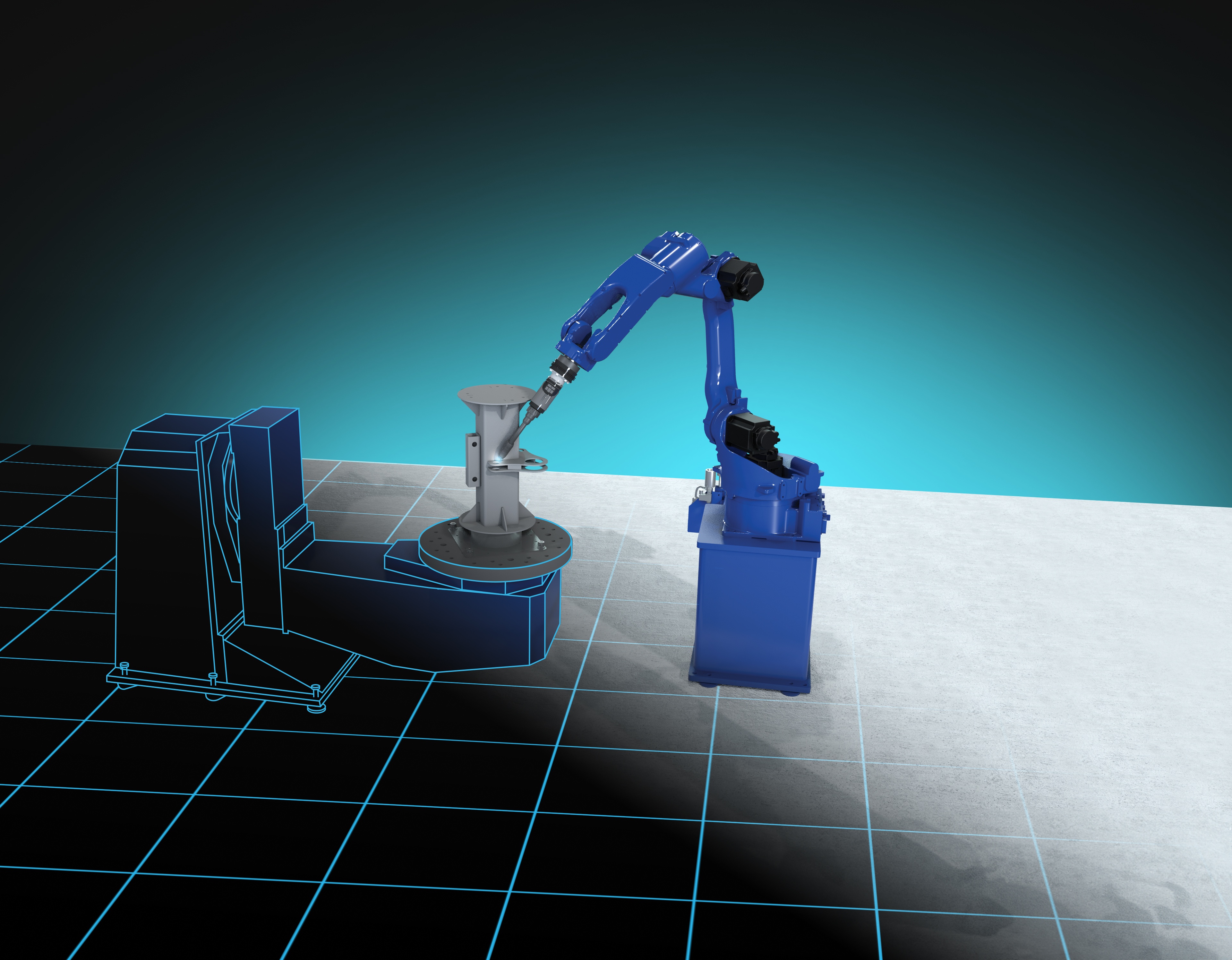
Traditionally, robot programming required interpreting 2D drawings or loosely defined 3D models to manually define robot toolpaths—often using a teach pendant on the shop floor. Offline programming marked a major improvement, enabling robot programmers to work in a simulated environment without interrupting production, helping reduce downtime and errors.
Model-based engineering takes the next step by associating manufacturing data with the CAD model, allowing software to generate robot programs automatically. This results in faster setup times, reduced rework and easier adaptation to design changes—all key for high-mix, low-volume manufacturing environments.
What is model-based engineering—and why it matters
Model-based engineering is a methodology where the annotated 3D model drives design, planning and manufacturing processes. At its core is model-based definition—where manufacturing information is defined directly in the 3D model—and product manufacturing information as the underlying data. PMI includes details such as weld symbols, tolerances, material and process specifications.
To automate robot programming using this data, PMI must be accurate, complete and structured in a machine-readable format. This is where Capvidia plays a critical role. Their software MBDConnect helps extract PMI from native CAD files and convert it into neutral formats such as QIF, ensuring it meets open standards like QIF and STEP AP242. This validation step ensures downstream applications—like robotic programming—receive consistent, structured data.
With Capvidia’s MBDVidia tool, manufacturing and automation teams can review the validated model and its bill of characteristics (BoC), giving them a complete view of the annotated design. Once validated, this data flows into Visual Components OLP software, where it can be used to generate robot toolpaths automatically—accelerating workflows and reducing the need for manual input.
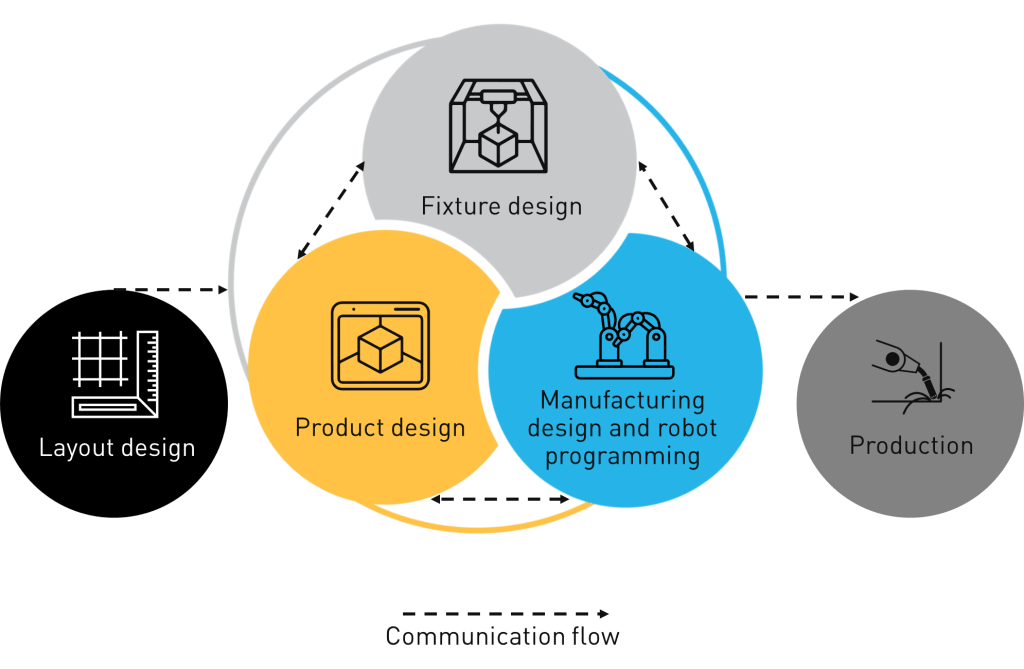
How MBD-based programming works in a manufacturing company
Model-based engineering creates a connected workflow where everyone—from design to the shop floor—works from the same 3D model.
Here’s how MBD-based robot offline programming works in practice, step by step:
Step 1: 3D Designer – define it once
The designer creates the 3D CAD model with weld symbols, geometric tolerances, dimensional requirements and material specifications. Using Capvidia plug-ins, the PMI is exported to a neutral QIF format and validated. MBDVidia provides a clear bill of characteristics (BoC) that consists of all PMI from the native CAD model, giving manufacturing engineers and programmers a complete reference for the design intent.
Step 2: Manufacturing Engineer – prepare the environment
The manufacturing engineer imports the validated QIF model into Visual Components. Their role is to configure the production setup: define fixtures, place parts and set up the robot cell layout. They also check the imported PMI to ensure all required manufacturing data is included and ready for programming.
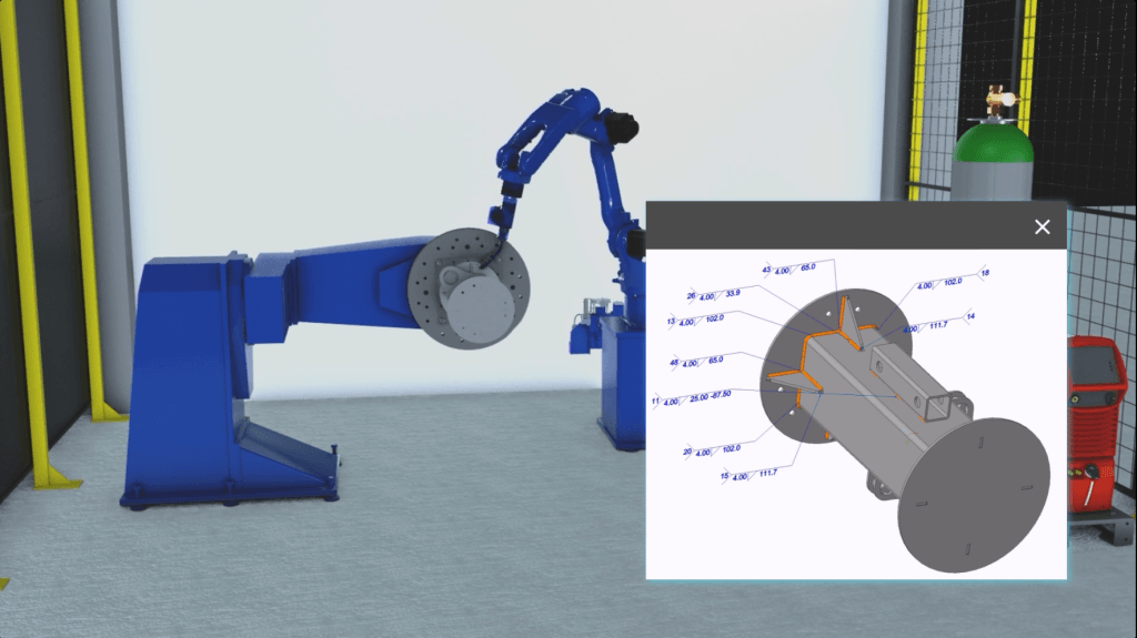
Step 3: Robot Programmer – let the software work
Visual Components OLP software automates the robot programming workflow from the start. It begins by reading the PMI from the QIF model or supported CAD formats to import weld definitions. From there, it automatically assigns and optimizes welding parameters, solves robot weld paths, generates and solves seam search paths, optimizes the welding sequence, solves via paths and handles postprocessing. The robot programmer’s focus shifts to reviewing results and fine-tuning motions if needed—manual programming is no longer required.
Step 4: Operator – press play
The operator loads the completed program onto the robot cell with minimal manual adjustments. Since the program is based on validated PMI and Visual Components OLP software validates and optimizes the robot programs, the results are accurate and error-free. This helps production start quickly and with confidence.
What you need to enable MBD-based robot offline programming
To enable this workflow and take advantage of MBD-based robotic automation, manufacturers need:
- CAD software that supports PMI (e.g., SolidWorks, Creo, Siemens NX)
- Capvidia tools to validate and export PMI to QIF
- Visual Components OLP software to automate robot programming from PMI
- Internal alignment on using MBD as a cross-functional data source across engineering and production
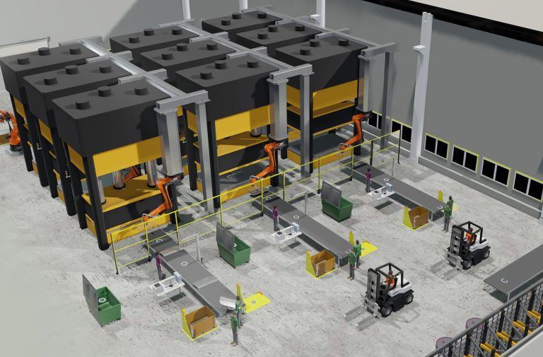
Pioneering MBD-based robot programming across industrial processes
While robotic welding is the most immediate and impactful application of MBD-based robot offline programming, this approach also supports workflows in automated inspection, robotic assembly and quality control. Once your 3D CAD model includes validated PMI—whether embedded or in a companion file—it builds on your existing digital workflows and becomes a reusable digital asset that drives efficiency across multiple manufacturing processes.
Model-based engineering enables a smarter, faster and more collaborative manufacturing process. With Capvidia helping validate and export PMI and Visual Components turning that data into actionable robot programs, manufacturers can close the gap between product design and manufacturing.
The future of robot programming goes beyond offline—it’s model-driven. Visual Components is at the forefront of making model-based engineering a reality in robotic welding and beyond.
Want to see MBD-based robot programming in action? Contact us to learn more.
Further reading
Optimizing manufacturing with simulation and robot offline programming
Manufacturers are increasingly relying on simulation and robot offline programming to master variant diversity, improve quality and keep cycle times predictable. This article explores how simulation, digital twins and offline...
Manufacturing simulation and robot offline programming as the foundation of digital production planning
Manufacturing simulation helps companies validate feasibility, optimize performance and reduce risk before building real systems. By combining production simulation with offline robot programming, manufacturers can test cycle times, robot reach,...
Fast and easy robot offline programming (OLP) for welding: a practical no-code workflow
Robot offline programming (OLP) makes robotic welding faster, more predictable and easier to manage, especially in high-mix, low-volume environments. This guide outlines the foundational OLP workflow, covering digital cell setup,...