Fast and easy robot offline programming (OLP) for welding: a practical no-code workflow
Robot offline programming (OLP) makes robotic welding faster, more predictable and easier to manage, especially in high-mix, low-volume environments. This guide outlines the foundational OLP workflow, covering digital cell setup, tools and frames, high-level weld path creation, robot–positioner synchronization, path validation and program export. The result is less touch-up, faster changeovers and consistent weld quality across varying parts.
Programming welding robots doesn’t need to be slow, complex or tied to the shop floor. Today, manufacturers can create accurate welding programs in a virtual 3D environment, automatically generate weld paths, validate collisions and joint limits and export robot-ready code, all without stopping production or writing a single line of code.
This guide walks through a fast, no-code robot offline programming (OLP) workflow for welding robots. It focuses on the core steps that lay the foundation for detailed robot programming and advanced weld path optimization. The process begins with building the welding cell digitally and continues through one-click weld path generation, path validation, simulation and post-processing. It’s designed for high-mix, low-volume environments where speed, flexibility and repeatability matter most.
1. Build your welding cell in the 3D environment
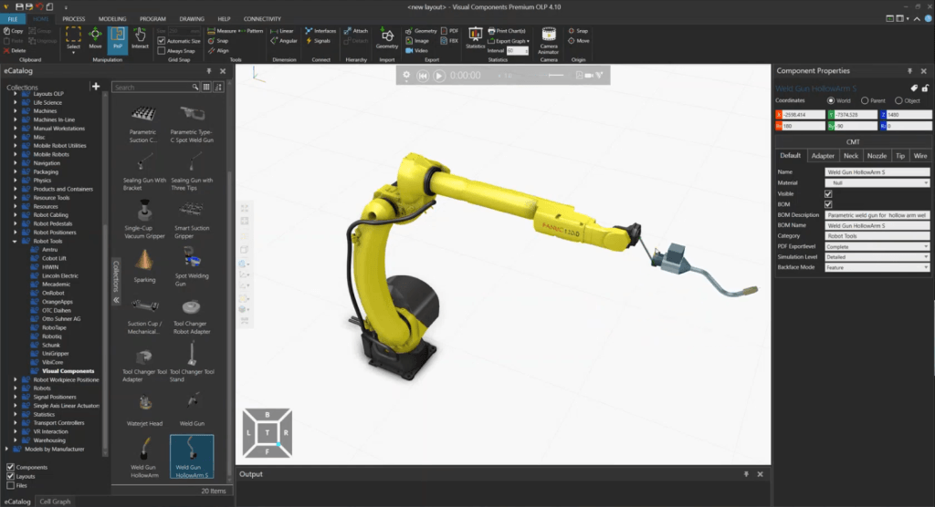
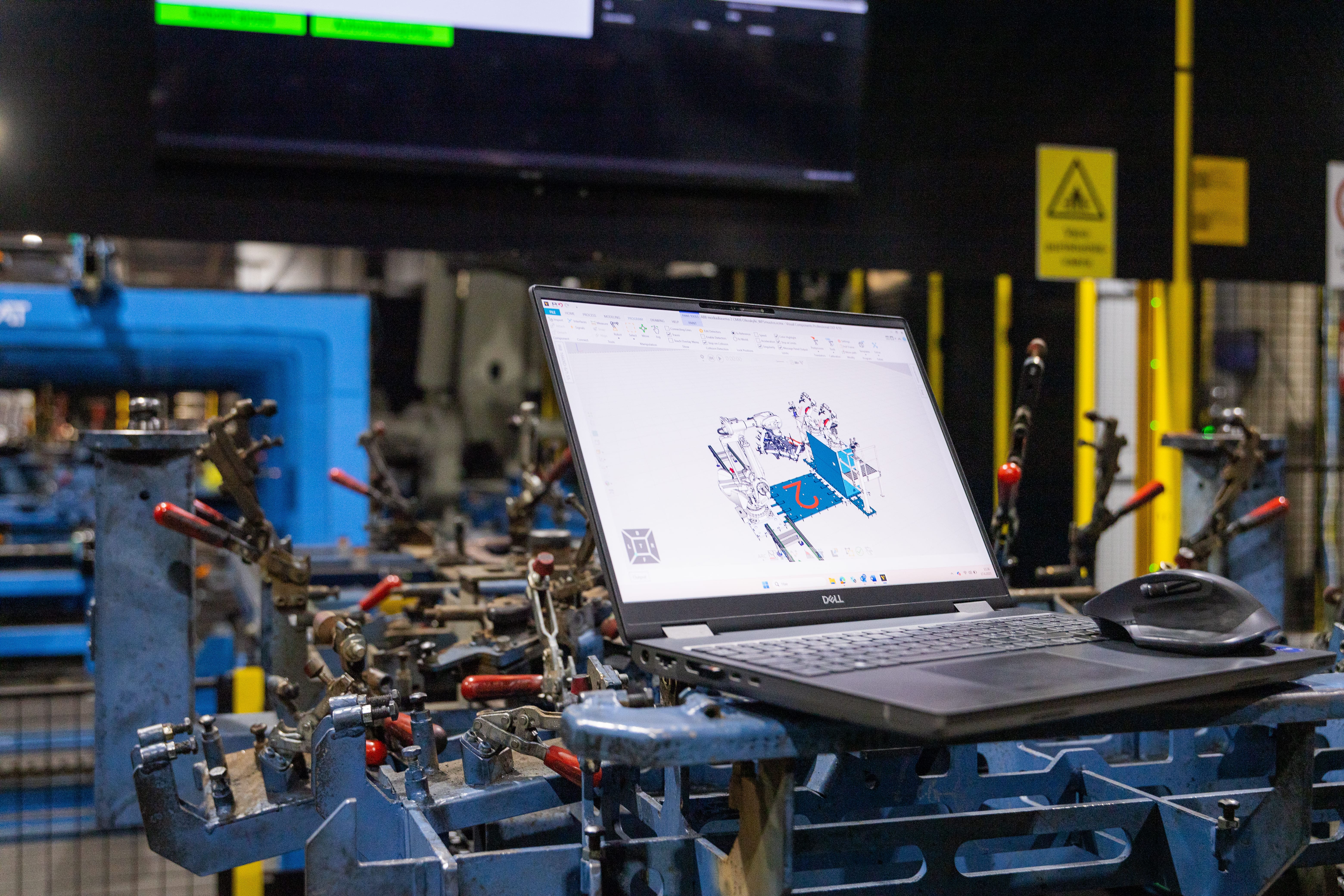
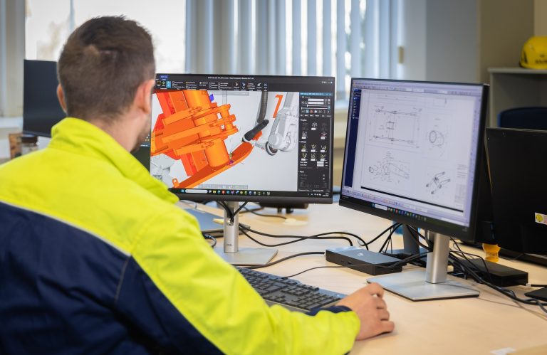
The workflow starts with an accurate digital representation of your welding cell. In Visual Components, you assemble the layout by selecting the robot model you use in your production, like a FANUC ARC Mate 120iD arc welding robot used in our demonstration, along with the positioner, fixtures, welding torch and the workpiece or assembly.
You can drag and drop components from the eCatalog. Plug-and-play (PNP) features make attaching tools and parts simple. The closer your virtual layout matches the physical system, the more reliable the resulting program will be when transferred to the shop floor.
Why this matters: An accurate layout is the foundation for everything that follows, reach checks, collision detection and coordinated motion all depend on it.
2. Set up tools, reference frames and torch orientation
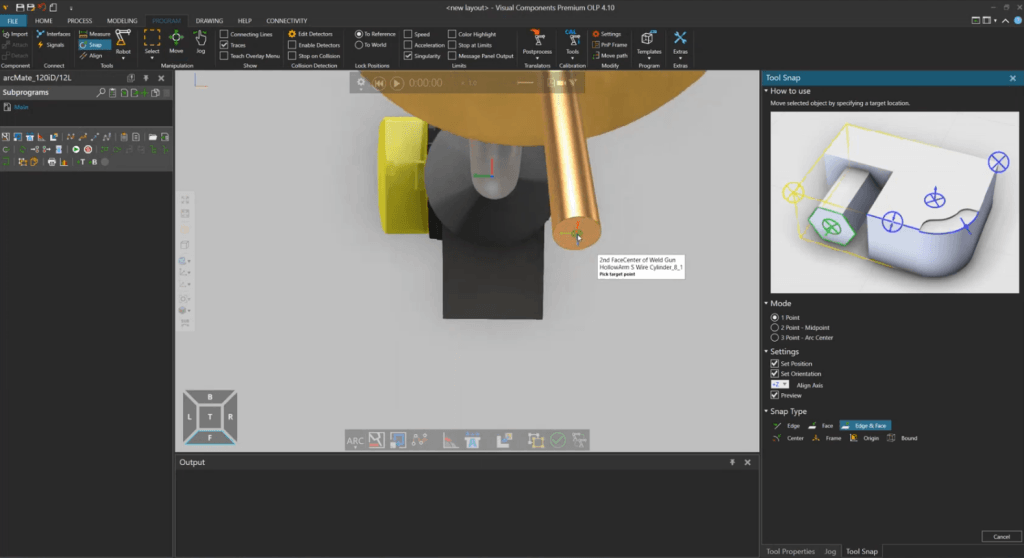
After creating the layout, the next step is defining the tool and reference frames used for path calculations. This includes:
- Tool center point (TCP): the precise tip of the welding torch
- Torch orientation: ensuring the digital torch matches the real welding angles
- Base frame of the workpiece: to align motion with the part
In our demonstration, we adjusted the TCP visually to reflect the actual wire-tip location and confirmed that the digital torch matched the physical one. Coordinate systems in Visual Components can be rotated as needed, for example, 180° on the X/Y axes, to match simulation conventions.
Calibrating these values correctly, especially the TCP and fixture positions, reduces touch-up on the real robot and ensures welds are accurate from the start. This step is essential for creating a reliable foundation before defining weld paths.
3. Synchronize robot and positioner motion
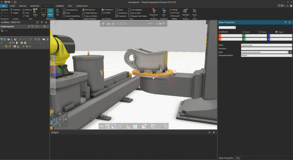
Many welding cells use single- or dual-axis positioners to present the weld optimally. Coordinating the robot and positioner manually can be complex, especially when multiple axes need to move in sync.
In Visual Components OLP, the software automatically synchronizes robot and positioner motion so the torch maintains the correct orientation throughout the weld. Engineers can also fine-tune angles or override synchronization if needed, giving control without extra programming effort.
This approach reduces trial-and-error adjustments on the shop floor, improves weld consistency and accelerates preparation for high-mix production.
4. Validate reachability and collisions early
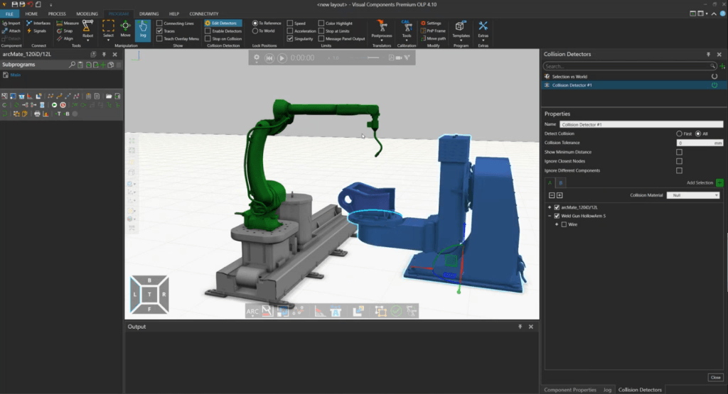
Before creating weld paths, it’s important to ensure the robot can reach tall weld locations without colliding with fixtures or exceeding joint limits. Visual Components OLP allows you to enable collision detection, observe motion around tight areas, evaluate singularities and review torch-angle constraints that affect weld quality.
Identifying potential issues in the virtual environment prevents costly downtime and errors on the physical robot. Ensuring that all programmed paths are feasible and safe before production begins is critical to reliable welding automation.
5. Create the welding path
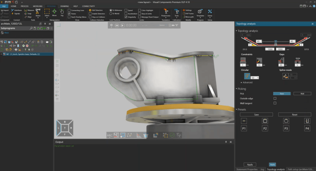
With the environment set up, you can start defining the welding path. At a basic level, weld path creation in OLP focuses on defining where and how the weld happens. In Visual Components OLP, welds are created by selecting start and end points, setting the torch angle and adding approach and retract motions. Travel speeds and welding parameters are also configured at this stage.
The demo highlighted that linear (yellow) and circular (orange) motions are automatically detected, simplifying complex contours. While this step is usually the most time-consuming on a teach pendant, OLP streamlines the process by allowing visual adjustments of angles and transitions, particularly helpful for long seams or intricate paths. You can also rotate or roll the torch to optimize the robot’s kinematics, applying changes across the entire weld path in a single step.
This step emphasizes visual feasibility and repeatability, allowing engineers to create reliable weld paths quickly, while detailed parameter optimization can be addressed in more advanced workflows.
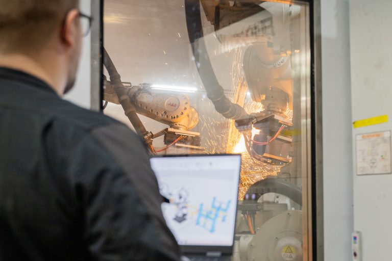
6. Validate the welding sequence in simulation
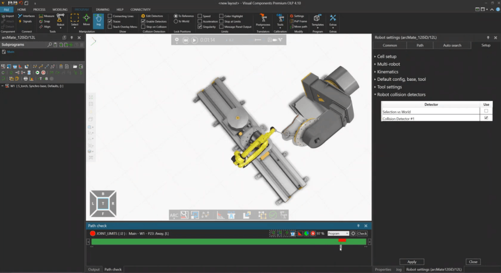
After creating the weld paths, the complete program is tested in simulation before sending to the robot. You can run the full cycle to check for collisions, verify transitions, monitor joint behavior and confirm torch orientation.
Cycle time can be estimated by using internal motion models for a quick estimate or connect a virtual robot controller for timing that reflects the real robot more closely. The goal is to ensure every motion is feasible before you export the program, helping identify bottlenecks, optimize production and reduce verification time or the need for trial-and-error adjustments on the shop floor.
7. Export robot programs efficiently
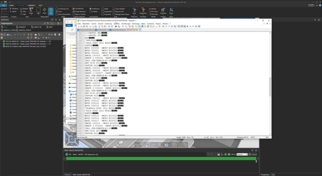
After simulation and virtual validation, Visual Components OLP allows you to export the program in the native format of your robot brand. This includes motion commands, frames, positioner instructions and the welding parameters required by the controller.
Because most issues have already been addressed offline, once the program is transferred to the robot, only minor touch-up is typically needed to account for small calibration differences. Python-based post-processors are available for customization if needed, allowing adjustments to controller-specific syntax. From there, the robot is ready for production.
This workflow enables faster changeovers, consistent weld quality and minimal disruption to ongoing production.
Why this workflow matters for welding automation
For many manufacturers, especially in high-mix environments, OLP provides a practical way to increase flexibility without sacrificing throughput. Programming robots becomes faster and more consistent and engineers can prepare new jobs ahead of production. For welding applications, where angles, approach paths, joint limits and positioner coordination are critical, being able to review and validate everything visually before sending the code to the robot is particularly valuable. This leads to shorter changeovers, fewer errors and better use of both robots and people.
FAQ about robotic welding and offline programming
Accuracy depends on how closely the virtual cell matches the physical one. When the TCP, reference frames, and fixture positions are calibrated correctly, offline programs can be very accurate. Only minimal touch-up is typically required on the real robot.
Yes. You can store and reuse welding parameters including torch angles, weaving, speeds, approach distances, and multi-pass practices. This supports consistent quality and speeds up programming of similar product families.
Yes. Visual Components allows you to estimate cycle time using internal motion models or connect a brand-specific virtual controller for more accurate timing. This helps validate throughput and identify bottlenecks before production.
Visual Components OLP can automatically coordinate robot and positioner axes to maintain proper torch orientation throughout the weld. You can also override or adjust the synchronization manually when needed.
Yes. Because all programming and verification happen offline, robots continue welding while new programs are being developed. This is especially helpful for high-mix environments where changeovers are frequent.
Visual Components OLP 5.0 supports 22 robot brands, including ABB, FANUC, Yaskawa, KUKA, Kawasaki, and others. With access to more than a thousand robot models, you can design and program welding cells regardless of the equipment mix in your factory.
Yes. You can define your multi-pass logic, set up the layers, and save them in your process library. The system does not automatically generate multi-pass logic, it reuses the logic you define, keeping you in control.
Not necessarily. OLP automates path solving, simulation, and template application, so engineers with welding knowledge but limited robot experience can create reliable programs.
Yes. Torch rotation and TCP adjustments can be applied to the entire weld path or specific points, improving robot reachability and optimizing welding angles without reprogramming the entire sequence.
Further reading
Automated robot programming: automated path creation in minutes
Automated robot programming reduces hours of manual work by shifting path creation and validation to the offline programming software (OLP). This article explains how automated programming works in practice, the...
Complete guide to ABB robot programming and offline programming
Master ABB robot programming with offline programming (OLP). This comprehensive guide explains how to efficiently program MultiMove synchronized welding cells, streamline the OLP workflow and choose the right software, ABB...
Optimizing manufacturing with simulation and robot offline programming
Manufacturers are increasingly relying on simulation and robot offline programming to master variant diversity, improve quality and keep cycle times predictable. This article explores how simulation, digital twins and offline...